Transcription of Hospital Operating Room Ventilation Systems - ASHRAE
1 ASHRAE journal MAY 201814 TECHNICAL FEATUREK ishor Khankari, , is president at AnSight LLC in Ann Arbor, Fluid Dynamics (CFD) Analysis of Hospital Operating Room Ventilation Systems BY KISHOR KHANKARI, , FELLOW ASHRAEThe primary objective of Hospital Operating room (OR) Ventilation Systems is to mini-mize surgical site infection due to airborne contaminants and bacteria and to provide a comfortable environment for surgeons and other staff in the room. The key factor in reducing surgical site infection is to minimize the contamination of the sterile (clean) zone where the surgical procedures are performed. One source of infection in the OR is squames, which are skin scales shed from the exposed skin of occupants in the Once airborne, these bacteria-carrying particulates generally follow the path of airflow in the room. The OR Ventilation system should effectively sweep these particulates out of the sterile zone and minimize their re-entrainment from non-sterile (contaminated) Standard 170-2017 2 provides minimum requirements for the design and layout of the ventila-tion Systems in Operating rooms which presumably can maintain a sterile environment around the surgical site.
2 According to this standard, diffuser array should provide airflow over the patient and surgical team. Furthermore, the coverage area of the primary supply diffuser array should extend a minimum of 12 in. (305 mm) beyond the footprint of the surgical table on each side. The room should be equipped with at least two low sidewall exhaust grilles placed at opposite corners, with the bottom of these exhaust grilles installed approximately 8 in. (203 mm) above the floor. In addition, the OR should maintain positive pressure with a total of 20 air changes per hour (ACH) supplied with 4 ACH outside air. The supply air should be unidirectional directed downward with an average discharge velocity of 25 to 35 fpm ( to m/s). These specifications for minimum discharge veloci-ties are based on previous CFD studies, which concluded that such velocities and the coverage area of the diffuser array would overcome the rising buoyant plumes from the sensible heat sources ( , surgical lights in the ster-ile zone), as well as protect the surgical site by allowing a local thermal plume to develop from a relatively warm surgical The later assumption, however, could not be verified by the ASHRAE -funded research project on Part I: Analysis of Air Change RatesThis article was published in ASHRAE journal , May 2018.
3 Copyright 2018 ASHRAE . Posted at This article may not be copied and/or distributed electronically or in paper form without permission of ASHRAE . For more information about ASHRAE journal , visit 2018 ASHRAE JOURNAL15experimental evaluation of Hospital OR Ventilation It should be noted that the role ASHRAE standards is to provide only minimum requirements, which may not be the optimal design is the primary carrier of heat, moisture, contami-nants, and airborne particulates in Operating rooms. The distribution of supply air and the associated flow path of the air determine the resulting air velocities, temperature, and concentration of contaminants, and flow path of air-borne particulates at various locations in the room. Such distribution, in turn, determines thermal comfort, air quality, and potential for transmission of airborne particu-lates.
4 Ideally, in an Operating room the supply air should pass through the sterile zone and exit through exhaust grilles in a single pass manner without recirculation and mixing with the supply airstream. It is generally believed that high air change rates can yield a cleaner environment in the Operating rooms. However, recent studies indicate increasing ACH does not necessarily provide a cleaner envi-ronment but substantially increases the Operating airflow patterns, temperature distribution, and resulting flow path of airborne contaminants can depend on several interrelated factors including the location, type, and number of supply diffusers; supply air change rates and supply air temperature; locations and strengths of various heat sources in a room, including the ambi-ent and surgical lights; size and location of equipment in the room that can obstruct the flow path of the air and contaminants; size and locations of room returns; and perhaps also on the frequency of opening and closing OR doors.
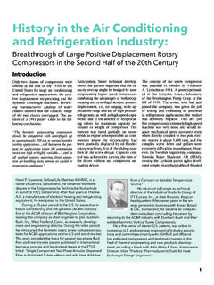
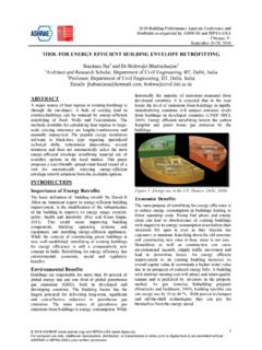
5 Physical testing and real time measurements of all the parameters that can affect the performance of the OR ACH = 23 ACH = 15 ACH = 31 FIGURE 1 Diagram of CFD model of a Hospital Operating room. (Left) Isometric View. (Right) Plan MachineLaminar Diffusers (9)Overhead LightsDoor Leakages (2)Waste DisposalReturn Grilles (2)Back TableScreensSurgical Lights (2)AnesthesiologistBack TableScrubbing NurseFIGURE 2 Airflow patterns at central plane in the Operating room for three differ-ent ACH showing similar airflow patterns; with air recirculation and entrainment at the edge of the sterile journal MAY 201816 TECHNICAL FEATURE FIGURE 3 Contours of air velocity at central plane in the Operating room for three different ACH rates showing the discharge air accelerates as it approaches the Operating table, with higher velocity zones (shown in red) occurring near the edge of the sterile zone at higher 4 Contours of air temperature at central plane in the Operating room showing thermal stratification occurs at all three different ACH, and increasing ACH minimizes the contraction of the supply air jet and decreases the average temperature in the system including the airflow patterns and the resulting flow path of contaminants is not feasible, if not ,4,5,6 In such situations CFD analyses may pro-vide a feasible alternative based on sound scientific laws of physics, including laws of air motion and heat transfer.
6 CFD analyses provide detailed three-dimensional visu-alization of airflow and temperature distributions ulti-mately leading to valuable insights of airflow patterns and the resulting flow path of airborne main objective of this CFD study is to evaluate the impact ACH on the airflow patterns, temperature distribution, and on the probable flow path of airborne particulates in a typical OR. This study also attempts to analyze the impact of supply airflow rates on the entrain-ment of the surrounding air into the sterile zone by evalu-ating the acceleration of centerline velocity of the supply air jet. A follow-up CFD study, which will be published in a future issue will analyze the impact of HVAC configura-tion on the performance of OR Ventilation Setup of the Operating RoomA three-dimensional, steady-state, non-isothermal ACH = 15 ACH = 23 ACH = 15 ACH = 23 ACH = 31 ACH = ( F) journal MAY 201818 TECHNICAL FEATURE ACH = 15 ACH = 23 ACH = 31 FIGURE 6 Flow path of airborne particulates originating from the anesthesiologist at the edge of the sterile zone demonstrating particles being swept from the sterile zone into the non-sterile zone before exiting the OR, at three different model of a Hospital OR is developed for this study as per the minimum requirements stated in Standard The room has about 560 ft2 (52 m2) floor area (28 20 ft [ 6 m]) with 10 ft (3 m) ceiling height.
7 As shown in Figure 1 (page 15), the virtual OR has an Operating table with a patient, two surgeons, two nurses, anesthesiolo-gist, surgical lights, overhead lights, and several other pieces of equipment and furniture. These are sources of sensible heat and also obstructions to the airflow. Most of these entities are located within the sterile zone (under the array of laminar unidirectional diffusers) except the scrubbing nurse and the back table. The air is supplied through a single array of nine laminar flow dif-fusers (72 ft2 [ m2]) located at the center of the room ceiling. The room air is exhausted through two exhaust grilles located on opposite walls and through the leak-age openings located under the two doors. The effect of supply airflow rate is analyzed by varying the diffuser ACH = 15 ACH = 23 ACH = 31 FIGURE 5 Flow path of airborne particulates originating from the occupants inside the sterile zone demonstrating particles being swept from the sterile zone into the non-sterile zone where they recirculate before exiting the OR, at three different 2018 ASHRAE JOURNAL19 TECHNICAL FEATURE discharge air velocity from 20, 30, and 40 fpm ( , , and m/s), which correspond to 15, 23, and 31 ACH, respectively.
8 The exhaust flow rate through the exhaust grilles was maintained lower than the supply flow rate such that the exhaust flow rate (leakage) through the two door openings remains at 350 cfm (165 L/s), and thus, the room was maintained at positive sensible heat loads due to the occupants and the overhead lights were assumed to be 1500 Btu/h (440 W) and 2457 Btu/h (720 W), respectively. The total sensible heat load due to the other equipment, including the anes-thesia machine, screens, surgical lights, and monitors was assumed to be 3583 Btu/h (1050 W). Thus, the total sensible heat load in the room was assumed to be 7,540 Btu/h (2210 W). The supply air temperature was set at 67 F ( C) which maintained the average room temperature at 70 F (21 C). The supply airflow rate at 30 fpm ( m/s) is in accordance with the minimum requirements in ASHRAE Standard This study did not analyze the transport of moisture and resulting relative humidity in the standard k-epsilon (k-e) turbulence model was employed to compute the turbulent viscosity of the air.
9 The probable flow paths of airborne particulates are analyzed by tracking the airflow path streamlines released from the occupant s faces which are probably the most exposed skin surfaces of the surgeons. The particulates are assumed to be skin squames which are about 10 microns in This analysis assumes most of the airborne particles released from the occu-pant s faces would follow the flow path of the air. Particles less than 20 microns can readily follow the flow path of the Since the main goal of the proposed analysis is to analyze the flow path of airborne particles, any settling and deposition of these particulates on the surfaces is not explicitly considered in this study. Results and DiscussionAirflow PatternsThe analyses for three different supply airflow rates show similar airflow patterns (Figure 2, page 15). In all three cases, the air from the non-sterile zone entrains at the edges of the sterile zone.
10 While the air near the floor moves away from the sterile zone towards the exhaust grilles, the air in the middle and upper sections of the room moves from the non-sterile zone into the ster-ile zone. Also, in all three cases the discharge air from the laminar diffusers accelerates as it approaches the Operating table (Figure 3, page 16). However, the location of this high velocity zone changes with the supply airflow rates. In the case of low airflow rate (15 ACH) the zone of high velocity is formed almost at the center of the sterile zone. In the case of higher airflow rates (23 and 31 ACH) the zone of high velocity moves towards the outer region of ACH = 15 ACH = 23 ACH = 31 FIGURE 7 Flow path of airborne particulates originating from the scrubbing nurse located outside the sterile zone showing entrainment of the particles back into the sterile zone for all three 201820 TECHNICAL FEATURE the sterile zone.