Transcription of Hot-Mix Asphalt Plant Operations
1 9727-05/Sec5 12/20/00 17:53 Page 39. P A R T. II. Hot-Mix Asphalt Plant Operations 9727-05/Sec5 12/20/00 17:53 Page 40. 9727-05/Sec5 12/20/00 17:53 Page 41. S E C T I O N. Types of Asphalt Plants: 5 Overview The purpose of an HMA Plant is to blend aggregate and transported by the gathering conveyor and transferred to Asphalt cement together at an elevated temperature to a charging conveyor. The material on the charging con . produce a homogeneous Asphalt paving mixture. The ag veyor is then carried up to the aggregate dryer. gregate used can be a single material, such as a crusher The dryer operates on a counter-flow basis. The ag . run aggregate or a pit run material, or it can be a combi gregate is introduced into the dryer at the upper end and nation of coarse and fine aggregates, with or without is moved down the drum by both the drum rotation mineral filler.
2 The binder material used is normally as (gravity flow) and the flight configuration inside the ro . phalt cement but may be an Asphalt emulsion or one of a tating dryer. The burner is located at the lower end of variety of modified materials. Various additives, includ the dryer, and the exhaust gases from the combustion ing liquid and powdered materials, can also be incorpo and drying process move toward the upper end of the rated into the mixture. Indeed, with Superpave the use of dryer, against (counter to) the flow of the aggregate. As additives is becoming more common. Use of additives the aggregate is tumbled through the exhaust gases, the can result in a need for more binder storage tanks, as material is heated and dried. Moisture is removed and well as silos for adding mineral materials.
3 Carried out of the dryer as part of the exhaust gas stream. There are three basic types of HMA plants currently The hot, dry aggregate is then discharged from the dryer in use in the United States: batch, parallel-flow drum- at the lower end. mix, and counter-flow drum-mix. All three types serve The hot aggregate is usually transported to the top of the same ultimate purpose, and the Asphalt mixture the Plant mixing tower by a bucket elevator. Upon dis . should be essentially similar regardless of the type of charge from the elevator, the aggregate normally passes Plant used to manufacture it. The three types of plants through a set of vibrating screens into, typically, one of differ, however, in operation and flow of materials, as four hot storage bins. The finest aggregate material goes described in the following sections.
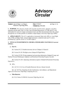
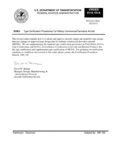
4 Directly through all the screens into the No. 1 hot bin;. the coarser aggregate particles are separated by the different-sized screens and deposited into one of the other hot bins. The separation of aggregate into the hot BATCH PLANTS. bins depends on the size of the openings in the screen The major components of a batch Plant are the cold- that is used in the screen deck and the gradation of the feed system, Asphalt cement supply system, aggregate aggregate in the cold-feed bins. dryer, mixing tower, and emission-control system. A The heated, dried, and resized aggregate is held in typical batch Plant is depicted in Figure 5-1; the major the hot bins until being discharged from a gate at the Plant components are shown in Figure 5-2. The batch bottom of each bin into a weigh hopper.
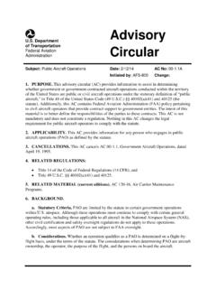
5 The correct Plant tower consists of a hot elevator, a screen deck, hot proportion of each aggregate is determined by weight. bins, a weigh hopper, an Asphalt cement weigh bucket, At the same time that the aggregate is being propor . and a pugmill. The flow of materials in a batch tower is tioned and weighed, the Asphalt cement is being pumped illustrated in Figure 5-3. from its storage tank to a separate heated weigh bucket The aggregate used in the mix is removed from located on the tower just above the pugmill. The proper stockpiles and placed in individual cold-feed bins. Ag amount of material is weighed into the bucket and held gregates of different sizes are proportioned out of their until being emptied into the pugmill. bins by a combination of the size of the opening of the The aggregate in the weigh hopper is emptied into a gate at the bottom of each bin and the speed of the con twin-shaft pugmill, and the different aggregate fractions veyor belt under the bin.
6 Generally, a feeder belt beneath are mixed together for a very short period of time . each bin deposits the aggregate on a gathering conveyor usually less than 5 seconds. After this brief dry-mix time, located under all of the cold-feed bins. The aggregate is the Asphalt cement from the weigh bucket is discharged AC 150/5370-14B. Appendix 1. 9727-05/Sec5 12/20/00 17:54 Page 42. 42 H O T - M I X A S P H A L T P A V I N G H A N D B O O K 2 0 0 0. F I G U R E 5 - 1 Typical HMA batch Plant . into the pugmill, and the wet-mix time begins. The mix is normally used as the primary collector. Either a wet ing time for blending of the Asphalt cement with the ag scrubber system or, more often, a dry fabric filter sys . gregate should be no more than that needed to com tem (baghouse) can be used as the secondary collection pletely coat the aggregate particles with a thin film of system to remove particulate matter from the exhaust the Asphalt cement material usually in the range of gases that flow out of the dryer and send clean air to the 25 to 35 seconds, with the lower end of this range being atmosphere through the stack.
7 For a pugmill that is in good condition. The size of the If RAP is incorporated into the mix, it is placed in a batch mixed in the pugmill can be in the range of separate cold-feed bin from which it is delivered to the to tonnes (2 to 6 tons). Plant . The RAP can be added to the new aggregate in When mixing has been completed, the gates on the one of three locations: the bottom of the hot elevator; the bottom of the pugmill are opened, and the mix is dis hot bins; or, most commonly, the weigh hopper. Heat charged into the haul vehicle or into a conveying device transfer between the superheated new aggregate and the that carries the mix to a silo from which trucks will be reclaimed material begins as soon as the two materials loaded in batch fashion. For most batch plants, the time come in contact and continues during the mixing process needed to open the pugmill gates and discharge the mix in the pugmill.
8 Is approximately 5 to 7 seconds. The total mixing time (dry-mix time + wet-mix time + mix discharge time) for a batch can be as short as about 30 seconds, but typi . PARALLEL-FLOW DRUM-MIX PLANTS. cally, the total mixing time is about 35 seconds. The Plant is equipped with emission-control devices, The parallel-flow drum-mix Plant is a variation of the comprising both primary and secondary collection sys old-style continuous-mix Plant . It consists of five major tems (see Section 12). A dry collector or knockout box components: the cold-feed system, Asphalt cement sup- AC 150/5370-14B. Appendix 1. 9727-05/Sec5 12/20/00 17:54 Page 43. S E C T I O N 5 Types of Asphalt Plants: Overview 43. F I G U R E 5 - 2 Major components of a batch Plant . ply system, drum mixer, surge or storage silos (see Sec The charging conveyor is equipped with two devices tion 11 for definitions of these silo types), and emission- that are used to determine the amount of aggregate being control equipment.
9 A typical parallel-flow drum-mix delivered to the Plant : a weigh bridge under the con . Plant is depicted in Figure 5-4; the major Plant compo veyor belt measures the weight of the aggregate passing nents are shown in Figure 5-5. over it, and a sensor determines the speed of the belt. The cold-feed bins are used to proportion the material These two values are used to compute the wet weight of to the Plant . A variable-speed feeder belt is used under aggregate, in tonnes (tons) per hour, entering the drum each bin. The amount of aggregate drawn from each bin mixer. The Plant computer, with the amount of moisture can thus be controlled by both the size of the gate open in the aggregate provided as an input value, converts the ing and the speed of the feeder belt to provide accurate wet weight to dry weight in order to determine the cor.
10 Delivery of the different-sized materials. The aggregate rect amount of Asphalt cement needed in the mix. on each feeder belt is deposited onto a gathering con The conventional drum mixer is a parallel-flow veyor that runs beneath all of the cold-feed bins. The system the exhaust gases and the aggregate move in combined material is normally passed through a scalping the same direction. The burner is located at the upper screen and then transferred to a charging conveyor for end (aggregate inlet end) of the drum. The aggregate transport to the drum mixer. enters the drum either from an inclined chute above AC 150/5370-14B. Appendix 1. 9727-05/Sec5 12/20/00 17:54 Page 44. F I G U R E 5 - 3 Flow of materials in batch tower. AC 150/5370-14B. Appendix 1. 9727-05/Sec5 12/20/00 17:54 Page 45.