Transcription of How RF Transformers Work and How They are Measured
1 AN-20-001 Rev.: B M150261 (04/15/15) File: document and its contents are the property of 1 of 15 HOW RF Transformers WORKAND HOW THEY ARE Measured CONTRIBUTIONS BY:DAXIONG JIHAIPING YANWEIPING ZHENGAUTHORED BY:FRED LEFRAKREVIEWED BY:RADHA SETTYAN-20-001 Rev.: B M150261 (04/15/15) File: document and its contents are the property of 2 of 15 HOW RF Transformers WORK AND HOW THEY AREMEASUREDAPPLICATIONS FOR RF TRANSFORMERSRF Transformers are widely used in electronic circuits forCImpedance matching to achieve maximum power transfer and to suppress undesiredsignal , current step-up or isolation between circuits while affording efficient AC between balanced and unbalanced circuits; example: balanced CIRCUITS AND impedance RELATIONSHIPSWhen signal current goes through the primary winding , it generates a magnetic field whichinduces a voltage across the secondary winding .
2 Connecting a load to the secondary causesan AC current to flow in the load. It is generally necessary to control terminating impedances of RF signal paths, especially inwideband applications where path lengths are not negligible relative to wavelength. WidebandRF Transformers are wound using twisted wires which behave as transmission lines, and therequired coupling occurs along the length of these lines as well as magnetically via the performance is achieved when primary and secondary windings are connected toresistive terminating impedances for which the transformer is designed. Transformers havinga turns ratio of 1:1, for example, are typically designed for use in a 50- or 75-ohm system.
3 In this application note, reference is continually made to terminating impedances which theuser should provide for Transformers , both for performance testing and in actual use. For thesake of consistency in the discussion, Transformers with turns ratio greater than 1:1 will bedescribed as step-up; that is, the secondary impedance is greater than the primary actual use, however, connection can be step-up or step-down as Figure 1, three transformer winding topologies are illustrated. The one in Figure 1a is the simplest. Called an autotransformer, this design has a tapped continuouswinding and no DC isolation. The transformer in Figure 1b has separate primary andsecondary windings, and provides DC isolation.
4 The RF performance of these configurationsis similar, however. The relationship of voltage and current between primary and secondarywindings, as well as the terminating impedances, are given by the following Rev.: B M150261 (04/15/15) File: document and its contents are the property of 3 of 15 Figure 1a Autotransformer Figure 1b Transformer with DC Isolation Figure 1c Transformer with Center-tapped SecondaryV = N V and I = I N, where N is the turns Since Z = V I and Z = V I , Z = N Z . That is, the impedance ratio is the square222111212of the turns secondary winding in Figure 1c has a center-tap, which makes the transformer useful asa balanced signal splitter; excellent amplitude and phase balance are obtainable with welldesigned RF Transformers having this configuration.
5 In the equations for Figure 1c which follow, the turns ratio N refers to the entire = N V, and V = V = N V 241 231 When the two halves of the secondary are connected to equal terminating impedances Z and2Z , then 3I = I = I N; Z = N Z , and Z = Z = Z 2 = N Z 2231412 3 4122AN-20-001 Rev.: B M150261 (04/15/15) File: document and its contents are the property of 4 of 15 Figure 2 High-frequency Transformer with Balun on Primary SideA variation on the transformer of Figure 1c, favoring high frequency performance, is shownin Figure 2. It adds a transmission-line transformer in cascade at the input, to convert anunbalanced signal to balanced at the input to the center-tapped transformer.
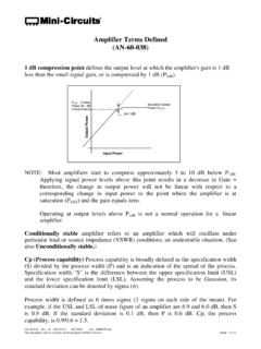
6 Features of thisdesign:CWide bandwidth, exceeding 1000 amplitude and phase return loss (lower VSWR) at the primary PERFORMANCE CHARACTERISTICSI nsertion Loss and Frequency BandwidthInsertion loss of a transformer is the fraction of input power lost when the transformer isinserted into an impedance -matched transmission system in place of an ideal (theoreticallylossless) transformer having the same turns ratio. Actual insertion loss is affected by non-idealcharacteristic impedance of the transformer windings, as well as winding and core insertion loss variation with frequency is illustrated in Figure 3 which shows the 1 dB,2 dB, and 3 dB bandwidths, referenced to the midband loss as they are usually loss at low frequency is affected by the parallel (magnetizing) inductance.
7 At lowtemperature, low-frequency insertion loss tends to increase because of decreasing permeabilityof the magnetic core. High-frequency insertion loss is attributed to interwinding capacitance,series (leakage) inductance, and core and conductor losses. At high temperature it tends tobecome greater due to increase in the loss component of core Rev.: B M150261 (04/15/15) File: document and its contents are the property of 5 of 15 Figure 3 Typical Frequency Response of an RF TransformerA further influence on transformer insertion loss is high AC or DC current. Most RFtransformers are used in small-signal applications, in which typically up to 250 mW of RF or30 mA of unbalanced DC current pass through the windings.
8 In the interest of small size andwidest bandwidth, the smallest practical size of cores is used. When insertion lossspecifications must be met with greater RF power or DC current applied, this must be takeninto account in the transformer design to prevent saturation of the magnetic core andconsequent bandwidth is insertion loss of a transformer Measured ? This question is especially pertinent forimpedance ratios other than 1:1 because accommodation must be made for the impedance oftest instrumentation, which is generally a constant 50 or 75 ohms. There are three methods:CThree Transformers are tested in pairs: A and B, A and C, B and C. Each pair ismeasured back-to-back; that is, the high- impedance windings are directly connectedto one another, and the low- impedance windings face the source and detector of theinstrumentation which match the transformer impedance .
9 This results in 3 values ofcombined insertion loss, so that the values of the 3 unknowns (the individual A, B, Cinsertion losses) can be transformer is Measured individually with a minimum-loss pad as a matching circuitconnected between the high- impedance winding and the instrumentation. This has beenfound practical for testing 50-ohm to 75-ohm Transformers , for which matching padsare readily available. The loss of the matching circuit (in dB) has to be subtracted fromthe Measured value to yield the insertion loss of the transformer itself. This method isapplicable where only 2 connections are made to the Rev.: B M150261 (04/15/15) File: document and its contents are the property of 6 of 15 Figure 4 shows the performance of a 50- to 75-ohm transformer, model , tested bythis method.
10 The loss of the matching pad was determined by measuring two of them back-to-back, and dividing the dB-value by the transformer has a center-tapped secondary winding , then it can be connected asa 180E power splitter. Each half of the secondary must be terminated by a matchingimpedance N Z 2, referring to the equations given for Figure 1c. This requires a21matching network to be used between the transformer and the sensing test-port of theinsertion loss instrumentation. Because an individual test port sees only one output,both 3 dB for the split and the loss of the matching network must be subtracted fromthe Measured value of insertion loss. By sensing both outputs, amplitude and phaseunbalance can also be Measured by this method.