Transcription of How Sheave Size Affects Wire Rope Strength. Severe bending ...
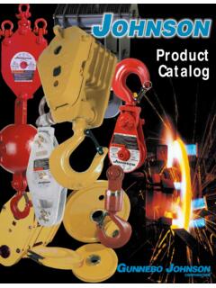
1 How Sheave Size Affects Wire Rope Strength. Severe bending is a major cause of short rope life . By contrast, the larger the Sheave diameter, the less wear on the rope and the greater its strength efficiency. Study the graph "Strength Efficiency of Wire Rope vs. Sheave Ratio." It confirms how readily the Strength Efficiency of the rope (a comparison of its strength when bent around a Sheave and tested in a straight sample) is affected by the Ratio. As one can see from this graph, the minimal 16 to 1 ratio required for the construction industry results in a wire rope strength efficiency of 90 percent. Accompanying chart shows which Johnson Manufacturing sheaves are necessary to comply with ANSI or CMAA standards. Translating ratios in terms of the closest appropriate Outside Diameters, the list ranges from an 8 inch hoisting block Sheave to a 48 inch overhead crane block Sheave .
2 Note that the hoisting block figures shown in this chart are based on the 16 to 1 ratio and in some cases are below the minimum size suggested by Johnson Manufacturing. Since the Outside Diameter of a Sheave is 1 to 2 inches greater than the Pitch Diameter, we recommend a Sheave diameter at least 20 times that of its rope. *16 to 1 ratio required for hoisting blocks by ANSI (Crawler, Locomotive and Truck Cranes) and ANSI (Mobile Hydraulic Cranes). ANSI is required by OSHA regulations as printed in Federal Register on June 24 and 27, 1974 **24 to 1 ratio required for running sheaves with 6 x 37 rope by CMAA Specification No. 70 (Electric Overhead Traveling Cranes). SAFE WORKING LIMITS OF WIRE ROPE BY SIZE, LINE PARTS* For Bronze Bushed and Roller bearing Load Blocks 6 X 25 Filler Wire Type W 1 WRC IPS Hoisting Rope** *The Figures presented are based on a Design Factor of 4 to 1 and apply to new ropeion with regard to rope size rests with the field CTURERS RECOMMEND DESIGN FACTORS OF 5 only.
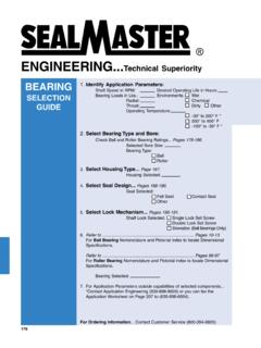
3 Please note that the final decisuser and that WIRE ROPE MANUFAAND 6 TO 1 FOR HOISTING LINES. e, use 115% of figure in table. For fiber core *For Extra Improved Plow Steel Ropire rope, use 93% of figure in table. *w How to Determine Common Loads and Forces in Block Applications. Three questions are often encountered in dealing with field problems: 1. How do I figure the number of line parts? 2. How do I figure the lead line pull required? 3. How do I figure the lifting capacity available from a given lead line pull? Needless to say, there are no "pat" answers. Conditions and equipment will vary from job to job. There are unaccountable losses in efficiency due to friction and general parts wear. Thus, the chart shown is offered only as a general guide.
4 The chart shows the relationship of the line parts to the mechanical advantage for a block system, including those sheaves in the top block or boom point. New bearings and wire rope are assumed. The basis for the charted curves is as follows: Load to be lifted (W) M = Mechanical Advantage = Lead Line Pull (P) M = Number of Line Parts (N) X Efficiency (E) N (K - 1 S E = Efficiency = K (K-1) K = bearing constant: for bronze for roller bearings S = Total number of sheaves in traveling block and top block or boom point N = Number of line parts supporting load To figure Line Parts (N) when you know Load to be Lifted (W) and Lead Line Pull available (P); 1. Divide W by P to get Mechanical Advantage W (M) needed - M = P 2.)
5 Enter the chart at the M value calculated. Move over to the curve which corresponds with your Sheave type and drop down to the bottom of the chart to find the correct number of line parts. Example: Load (W) = 40 tons Lead Line Pull available (P) = 5 tons W 40 M = P = 5 = 8 On Chart, read: 9 parts of line (roller bearing ) 10 parts of line (bronze bushed) To figure Lead Line Pull (P) needed when you know Load to be lifted (W) and Number of Line Parts (N): 1. Enter the chart at the number of line parts. Move up to the curve that corresponds to your bearing type and across to the vertical M scale to find the Mechanical Advantage available from your line parts. 2. Divide the Load (W) by the Mechanical Advantage (M) to get the Lead Line Pull required (P).
6 Example: Load (W) = 75 tons Line Parts (N) = 10 With roller bearing sheaves, 10 parts of line will give a Mechanical Advantage of 9 150,000 lbs. 16,666 lbs. required P = 9 = Lead Line Pull To figure Lifting Capacity available when you know Number of Line Parts (N) and available Lead Line Pull (P): 1. Enter the chart at the number of line parts. Move up to the curve that corresponds to your bearing type and over to the M scale to determine your Mechanical Advantage. 2. Multiply your Lead Line Pull (P) by the Mechanical Advantage (M) to determine Load (W) that can be lifted. W = P X M. Example: Lead Line Pull(P) = 10 tons Line Parts (N) = 12 For roller bearing sheaves, note Mechanical Advantage of W = P X M = 10 X = 106 tons 3.
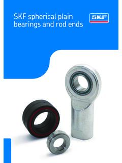
7 Be sure to use an adequate size wire rope. Consult "Safe Working Limits of Wire Rope," or wire rope manufacturer's recommendations. How to Account for The Extra Load in Top (Fixed) Block Applications All Safe Working Limits assigned Johnson Manufacturing products are based on traveling block applications. That is to say, applications in which the total load on the block is simply the load being lifted. With snatch and bail type construction blocks, however, it is not uncommon to attach the unit to the boom or gin pole tip, and in doing so, to increase the overall load on this unit by as much as 100 percent. This is because the load being hoisted, plus a reaction from the winch on the lead line, can produce a double load on an upper single Sheave block if the winch line angle is steep.
8 The accompanying figures show how factors of line pull and angle of lift combine to increase the load on the fixed block. To illustrate, let's say that a gin pole truck is being used to lift a weight of 2 tons, or 4,000 pounds. Angle of lift: 30 . There being no mechanical advantage to a single part load line system, the winch line pull is equal to 4,000 pounds, or the weight being lifted. The total load on the top single Sheave snatch block "A" is 4,000 pounds times the angle factor for 30 (See chart): Total load on A = 4,000 X = 7,720lbs. The total load on the tailboard block"B" is 4,000 pounds times the angle factor for 120 : Total load on B = 4,000 X = 4,000lbs. How to Figure Overhaul Weight Five pieces of information are needed to calculate the weight necessary to free-fall the block or overhaul ball: 1.
9 Size of wire rope to be used 2. Number of line parts 3. Type of Sheave bearings 4. Length of crane boom 5. Drum friction (Average, 50 pounds) Formula: TAKE - Weight of wire rope on backside of boom (Table I times boom length); ADD - Pull factor necessary to overcome friction (50 pounds); MULTIPLY - By overhaul factor for number of parts of line (Table II); TO FIND - Required weight of load block. Example: Required weight using 4- Sheave roller bearing block (8 line parts), 1-inch line, and 100-foot boom = [( X 100 ft.) + 50 lbs.] X = 2,059 lbs. Efficiency of Wire Rope Connections (Compared to SWL of Wire Rope) Wire Rope 100% Open Wedge Sockets, with clip 80% Zinc Type Sockets, properly attached 100% Clips 80%