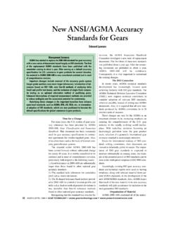
Transcription of How to Design and Install Bevel Gears ... - Gear Technology
1 How to Design and Install Bevel Gears for Optimum Performance: Lessons LearnedStephen MarshIntroductionBevel Gears must be assembled in a specific way to ensure smooth running and optimum load distribution between Gears . While it is certainly true that the setting or laying out of a pair of Bevel Gears is more complicated than laying out a pair of spur Gears , it is also true that following the correct procedure can make the task much easier. You cannot Install Bevel Gears in the same manner as spur and helical Gears and expect them to behave and perform as well; to optimize the performance of any two Bevel Gears , the Gears must be positioned together so that they run smoothly without binding and/or excessive Gears can include straight, spiral, Zerol, hypoid and Spiroid (to address the differences between each one is beyond the scope of this guide).
2 Because these types of Bevel Gears are basically conical in shape, they all have an optimum position for best performance. Usually the manufacturer of the Bevel gear determines this optimum position by running tests of individual gear sets. However, the gearbox designer and assembly technician share responsibility for incorporating this optimum positioning in the gearbox. The designer must provide shimming dimen-sions that are easy to measure in order to aid the fitter/techni-cian in assembling the overall gearbox.
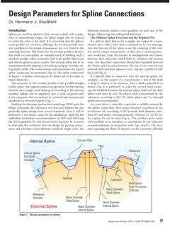
3 The aim of this guide is to provide instruction on how best to accomplish I: Key FactorsVarious parameters contribute to proper gearbox assembly that help ensure smooth and efficient operation; the two most important criteria are:1. Mounting distance2. BacklashMounting distance. The distance from a locating surface on the back of one gear (most commonly a bearing seat) to the center-line of a mating gear is the mounting distance (Fig. 1). In some cases, for convenience, a front surface may be used for the assembly.
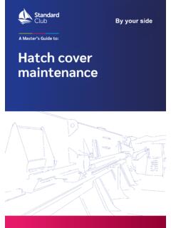
4 This is the most important parameter for ensuring correct and optimal , the pitch cone apex-to-crown-value is a fixed, nom-inal value determined by a formula. The dimension between the mounting surface (in Figure 2 it is the bearing seat) and the crown point will have a tolerance; it is common to see a toler-ance of mm up to mm. Obviously the mounting dis-tance is the addition of the two values and will therefore also have a straight Bevel Gears , the pitch cone apex is the intersection point of the pinion and gear axes (Fig.)
5 2).The pitch cone apex-to-crown-value is provided in engineer-ing handbooks and in publications provided by Gleason Corp., for example. Gleason publications include most of the informa-tion required by the gear designer to select a satisfactory pair of Bevel Gears . The pitch cone apex-to-crown value is determined by a formula that is a function of the pitch diameter, pitch angle and addendum; therefore, the pitch cone apex-to-crown-value cannot be chosen arbitrarily. However, the mounting distance is determined by the designer as long as the pitch cone apex-to-crown-value is maintained.
6 (Of course, in reality this mounting distance will have to have some degree of tolerance.) It may be possible to manufacture all Gears to the nominal mounting dis-tance specified on the drawing, but the additional cost to do so is usually not two Gears are being machined as a set, the manufacturer can establish the optimum value for this distance by running the gear set and adjusting its position to obtain a tooth contact pat-tern that is consistent with smooth running and optimum load distribution between mating gear teeth.
7 The optimum mounting distance can then be of dimensional variations between parts, each gear will have a unique value for the mounting distance and, in most cases, the manufacturer permanently marks this value onto each gear; the mounting distance will be within the tolerance Figure 1 Gear showing make-up of the mounting 2 Assembly of a pair of straight Bevel Gears (pinion and gear).60 GEAR Technology | June/July 2013[ ]technicalspecified on the drawing. Manufacturers aim for a tolerance of mm from the nominal value.
8 If, at assembly, the mounting distance of one or both Gears is made at less than the dimension specified, the teeth may bind, and excessive wear or breakage can result. If the mounting distance of either gear is made longer than the dimension specified, the Gears will not be in full mesh on a common pitch line and may have excessive The second most important variable for a pair of Bevel Gears is backlash , the space between mating gear teeth or the difference in width of the gear tooth and pinion tooth of the mating gear.
9 Unless otherwise specified, it is mea-sured at the tightest point of the is necessary to achieve correct operation of the Gears and varies with the size of the tooth and operating condi-tions. Bevel Gears are cut to have a definite amount of backlash when correctly assembled together. But excessive backlash or play, if great enough, can cause a sudden impulse or shock load in starting or reversing that may cause serious tooth damage. Excessive or insufficient backlash can also result in noise, exces-sive wear and damage.
10 Backlash can be changed by changing the position of one or both Notes for the Design EngineerGearbox housing/mounting. It is very important that the designer consider the mountings for the gear and pinion so that they are rigidly supported to handle all loads to which the Gears will be subjected in service. It is equally important that the designer detail the housing or mounting parts ( , bearing cap) with adequate tolerance for alignment, squareness, fits, and run-out, etc. While Bevel and hypoid Gears can accommodate rea-sonable displacements and misalignments without detriment to tooth action, excessive misalignment of the Gears reduces their load capability, with the consequent danger of surface failure and breakage while in should be made by the designer in the Design of the housing and mounting parts so that both the pinion and gear mounting distances can be adjusted.