Transcription of HOW-TO HOW-TO UNDERSTAND YOUR HOT AND COLD …
1 HOW- TO HOW-TO UNDERSTAND your . HOT AND cold water SYSTEM. F1. It is important that you are familiar with the supply and distribution of water in your home. Don't wait until you have a leak to realize that you cannot control the water and minimise damage. Time spent on investi- gating your water system will save trouble at a later date. This HOW-TO guide should be read in conjunction with HOW-TO : UNDERSTAND your Central Heating System. TOOLS. The following tools are useful in all emergencies and are also handy for maintenance. Adjustable spanner, 250mm Flat-bladed screwdrivers, with 3mm, 6mm and Adjustable spanner, 100mm 10mm tips. Square nose pliers Combination stop valve key, to fit fiin and flin square heads and fiin and flin tee handles 225mm footprint wrench Pozidrive Nos 1 and 2 screwdrivers C O L D W AT E R S U P P LY.
2 Most British homes are fed via pipes from a high pressure main in the road. This communication pipe runs to an external stop-valve (the water company stop-valve), adjacent to the property's boundary (F1). This stop-valve is set in a guard pipe below ground level. It may have either a square spigot or a tee spigot (F1). which may be turned on or off with a long-handled key (F1). Stop-valves only allow water to flow in one direction. This stops contaminated backflow into the mains supply. Some modern stop-valves are made of plastic, incorporate a water meter and are controlled by a short plastic key (F2). Under the lid is a moulded block of insulation material. Lift this out to operate the stop-valve and replace it afterwards. HOW - TO 1. F3. F2. HINT. Stop-valve guard pipes tend to fill up with mud and grit, until operating the valve becomes difficult.
3 Once a year, clean it out using an old tablespoon taped firmly to a long garden cane (F3). Use a combination stop valve key to ensure the valve operates correctly and smoothly (F1). SAFETY. In older properties one stop-valve may control water to two or more houses. You must inform your neighbours before turning off the water supply. Failure to do so could make you liable for any damage to their water and heating systems. water is fed from the external stop-valve via a service pipe to the point where it enters the house. This is usually referred to as the rising main (F1). It should be fitted with a stop-valve where it enters the house, usually under the kitchen sink. It might also be found in a downstairs cloakroom, in an understairs cupboard, under a trap in the floor or in a basement or cellar. HINT.
4 Lime may build up inside a stop-valve, preventing it from shutting. At least once a year, turn the valve fully off and on two or three times. When off, check that the flow has stopped by running the cold water tap in the kitchen sink. Don't force the valve shut with a spanner. If the flow doesn't stop, the washer needs replacing. HINT. Some old houses only have an external stop-valve. If you have this situation you would be wise to make fitting an internal stop-valve a priority for ease of access in an emergency. In multiple-dwelling buildings, the internal stop-valves may all be on the ground floor, on individual floors or in individual flats. HOW - TO 2. F4. I N T E R N A L W AT E R S U P P LY. There are two types of supply direct and indirect. A direct cold water supply has all of the cold water taps and sanitary appliances fed directly off the rising main.
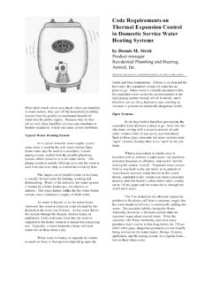
5 In old systems without check valves (F4), there is a risk of water becoming contaminated due to backflow ( water flows back into the mains) and such installations are no longer permitted in new housing. The hot water system is extremely inefficient and unable to supply central heating. HOW - TO 3. F5. A direct supply system fitted with a modern boiler, anti-syphon and backflow devices (F5) complies with most modern water by-laws and eliminates the dangers of bacterial contamination. This system is easy to install and maintain and, because the water is under constant mains pressure, the risk of freezing is reduced. It does, however, slightly increase the risks of leaking joints. This system is recommended where there is sufficient mains water supply to maintain a good quantity of water at adequate pressure during peak periods.
6 HOW - TO 4. F6. An indirect system (F6) supplies all sanitary appliances hand basins, showers, baths and WCs with water fed from a storage tank. Mains water , for drinking, is available at the kitchen tap only. This can also supply washing machines and a garden tap, which must be fitted with a check valve. The advantages of an indirect system include tank-fed water being at low pressure, reducing noise and the like- lihood of leaks. If they do occur, these produce less water and damage than a high-pressure system and there is less wear and tear on valves and washers. Pump boosted showers can only be fed from this type of system. The indirect system is more expensive to install (more pipe-work and tanks) and, unless properly installed and lagged, it is vulnerable to frost damage. Modern lagging enables this to be carried out easily.
7 If the water supply is cut off, the dwelling still has plenty of stored water for essential use. Recent water regulations insist that cold water storage tanks are fitted with kits to protect the water from contami- nation and infection, thus making the water potable (drinkable). HOW - TO 5. F7. domestic hot water SUPPLY. This term applies only to hot water for washing, cooking and cleaning. It does not refer to central heating water . Old direct hot water systems hot water in the cylinder is gravity fed from the water storage tank (F4). The water then circulates through a boiler and rises into the cylinder by convection (hot liquids and gases expand and rise, whereas cold ones contract and sink). This system is very inefficient. Pipes tend to clog up with lime scale, eventually causing the system to fail.
8 This system cannot supply central heating hot water . Modern direct hot water supply systems Mains water is fed into a combination boiler' where it is heated as it is called for, giving almost instantaneous hot water on demand (F5). The same boiler can be used for supplying hot water to a central heating system. The disadvantages are that baths tend to fill slowly if a tap is a long way from the boiler and quite a lot of cold water has to be drawn off before hot water appears. Indirect hot water supply water from the cold water storage tank is gravity fed into the bottom of the hot water cylinder (F6). The cylinder contains a heating coil (calorifier) connected to a boiler by a feed pipe and a return pipe for cooled water . This is the primary circuit'. water circulating in the primary circuit heats the coil, which in turn heats the domestic hot water in the cylinder.
9 Repeatedly heating the same water reduces lime scale build up. This circuit is filled and topped up by a pipe from the feed and expansion tank (header tank). The circuit may operate by gravity, but all modern installations are pumped (F7). The system is very efficient and may also run central heating. HOW - TO 6. F10. F8. F11. F9. EXPLANATION OF COMPONENTS IN DIAGRAMS. Overflow warning pipe (F4 7). This usually runs from the tank or cistern to the outside of the building. In some cases, a WC cistern overflow pipe may discharge inside the property in such a way that the water may be seen. The diameter of the overflow pipe is always larger than that of the supply pipe. This ensures that water will not overflow the edges of the tank or cistern. Drain taps may be straight or bent (F8). They may be combined with a stop-valve and all allow a system to be drained down.
10 A hose is attached to the nozzle or spigot and the tap opened with a small spanner or special key. F L O AT VA LV E S. Referred to in the past as ball-cocks, these are fitted to water storage tanks and WC cisterns to control water lev- els. As the float rises with the water level, it shuts off the valve at a predetermined point. The three most com- monly used float valves are: Portsmouth (F9). As the water level drops, the arm moves a piston away from a nozzle, allowing water to flow. Diaphragm or Garston (also known as BRE or BRS) (F10). The water inlet nozzle is closed by the action of the float arm pushing a plunger onto a rubber diaphragm. The filling action of this valve is gentler and quieter than the Portsmouth valve. Servo-diaphragm or Torbeck (F11). This operates in a more sophisticated way than the Garston valve.