Transcription of How to Order - Duhig
1 Pure-Flo . How to Order Table of Contents This brochure contains a comprehensive list of the figure number codes and description for each valve Introduction ..2. product option available at Pure-Flo Solutions Group. Valve Configurator Tool ..3. To assist in the ordering process, we have included How to Construct a Standard instructions on how to construct a standard valve Valve Figure Number ..4. figure number in proper sequence. You can also find Bodies and Polishes ..5. our valve configuration tool available at Diaphragms ..6. This Microsoft Excel tool is a Manual Bonnets, Actuator simple means of identifying valve product configura- Bonnets and Options.
2 7. tion and nomenclature. This tool will assist in select- Actuator Options ..8. ing compatible features and proper designation Switches and Actuator structure. Accessories ..9-10. Service Preparation and Quality Documents ..11. Obsolete Figure Codes ..12. Sterile Access and GMP. Fabrications ..13-14. Zero Static Fabrications ..15-17. Multiport Valves ..18-19. Terms & Conditions ..20-21. Office Locations ..22. 2. Pure-Flo Valve Figure Numbers Pure-Flo . Pure-Flo Microsoft Excel Valve Configurator Tool . To assist you in the specification develoment and ordering process we have a Microsoft Excel tool available at that will help you: select compatible valve features create correct figure numbers To access the tool: 1.
3 Hold your mouse over the Tools button and click on Valve Configurator from the dropdown list 2. Request a username and password if you do not already have one 3. Once registered, login with your username and password 4. After you have logged in, download the valve configurator tool To create figure numbers follow these steps: 1. Select valve type 2. Make feature selections 3. Continue making selections until no sections remain in yellow 4. Cells highlighted in red will explain cases where the selection of one feature requires the selec- tion of another feature (ex. 963 . bonnet requires M2 bonnet internals). 5. Click View/Print to see the resulting figure number with descriptions 6.
4 Click Save Line to Header to save the figure number configu- ration 7. Repeat steps 1-6 until you have all the figure numbers required Please contact your local Pure-Flo sales representative or Distributor for a demonstration or for assis- tance using the Microsoft Excel Valve Configuration tool. Resulting figure number with description 3 Pure-Flo Valve Figure Numbers Pure-Flo . How to Construct a Standard Valve Figure Number Valve Size Bodies and Polishes Diaphragm + + +. Page 4 Page 5 Page 6. Manual Bonnets, Switches and Actuated Bonnets, Actuator Options + + Actuator Accessories +. and Options Page 8. Pages 9-10. Page 7.
5 Service Preparation and Quality Documents Page 11. Constructing Figure Numbers Below are examples for constructing a manual and actuated valve figure number. The actuated valve example will be used to build a figure number on pages 4-11. Manual Valve Example Actuated Valve Example Figure Number: 1-F-419-6-0-0-TM17-963-M2-SQDB Figure Number: 1-F-428L-6-0-0-TM17-36-M7-A209- VSPS48-SQDB. Detailed description: 1: 1 inch size (DN25) Detailed description: F: Forged 316L SS 1: 1 inch size (DN25). 419: Triclamp Tube F: Forged 316L SS. 6: Interior Finish: Ra 25 Microinch Max 428L: 16 Gauge Extended Tangent Buttweld 0: Exterior Finish: No Mechanical Polish 6: Interior Finish: Ra 25 Microinch Max 0: No Electropolish 0: Exterior Finish: No Mechanical Polish TM17: Modified PTFE Diaphragm (FDA)/ Grade 17 0: No Electropolish 963: Plastic PAS Rising Handwheel with Travel Stop TM17: Modified PTFE Diaphragm (FDA)/ Grade 17 M2: Sanitary Internals 36: Plastic/PAS Actuated Bonnet SQDB: C of C Body CMTR M7: Bronze Compressor A209: Advantage Actuator, #209 Rev/ 90# Spring VSPS48: Value Switch Package, Silver Contacts 48V.
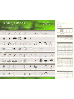
6 SQDB: C of C Body CMTR. Valve Size Size Figure Numer: 1- Code Description Configuration Example 1..25 .25 Inch (DN6) Size (in) 1..38 .38 Inch (DN10)..50 .50 Inch (DN15)..75 .75 Inch (DN20). 1 1 Inch (DN25). Inch (DN40). 2 2 Inch (DN50). Inch (DN65). 3 3 Inch (DN80). 4 4 Inch (DN100). 4 Pure-Flo Valve Figure Numbers Pure-Flo . Bodies and Polishes Body Type Body Ends (cont.) Tube Extension Code Description Code Description Code Description 2 Industrial Valve Body - Cast CF3M 495 ISO wall TE1 Valve End 1. Stainless Steel 496 ISO wall TE2 Valve End 2. 8 Bio-Tek Forged 316L Stainless Steel 497 ISO wall TEA Both Valve Ends & Purge End C Cast CF3M Stainless Steel 498 ISO wall TEB Both Valve Ends F Forged 316L Stainless Steel 499 ISO wall TEP Purge End N Body Not Supplied Spec Special End TE1P Valve End (P1) & Purge (P3).
7 S Swickle Body Cast CF3M Stn. Stl. SCREWED TE2P Valve End (P2) & Purge (P3). TBV Tank Bottom Valve 403 NPT Screwed TBVCR Tank Bottom Valve 316L BN2 FLANGED. W Wrought 316L Stainless Steel 433R ANSI Flanged w/ Raised Face Mechanical Polish - Interior Spec Special Material Body Code Description Second End Code 0 As Cast Body Ends Code Description 2 35 in Ra (.8 m) max Code Description 6 25 in Ra (.6 m) max CLAMP 7 15 in Ra (.38 m) max CLAMP X07 By Male Thread w/ Gasket Seat 8 20 in Ra (.5 m) max 409 Swagelok TS Fitting X09 Swagelok TS Fitting 9 11 in Ra (.28 m) max 410 Tri-Clamp Sch. 5 Pipe X10 By Tri-Clamp Sch. 5 Pipe 10 10 in Ra (.)
8 25 m) max 411 Min. Valine X11 By Min. Valine SFV1 BPE SFV1 Ra 20 Max 412 S Clamp X12 By S Clamp 413 Q Clamp X13 By Q Clamp SFV2 BPE SFV1 Ra 25 Max 414 I Line-Male X14 By I Line - Male SFV3 BPE SFV1 Ra 30 Max 415 I Line-Female X15 By I line - Female SFV4 BPE SFV1 Ra 15 Max, EP. 416 Swivel Nut X17 By Male Thread SFV5 BPE SFV1 Ra 20 Max, EP. 417 Male Thread X19 By Tri-Clamp Tube SFV6 BPE SFV1 Ra 25 Max, EP. 418 ISO Wall Tri-Clamp End X19S By Tri-Clamp Tube 18 Gauge 419 Tri-Clamp Tube X19S1 By Tri-Clamp Tube 20 Gauge Mechanical Polish -Exterior 419S Tri-Clamp Tube 18 Gauge X20 By Superior Code Description 419S1 Tri-Clamp Tube 20 Gauge BUTTWELD.
9 420 Superior X22 By Sch. 5 Pipe (ISO Body) 0 As Cast BUTTWELD X23 By 18 Gauge 1 Scotch Brite 422 Sch. 5 Pipe (ISO Body) X24 By 20 Gauge 2 25 in Ra (.6 m) max, Welds 423 18 Gauge X25 By Sch. 5 Pipe (ANSI Body) Scotch Brite 424 20 Gauge X26 By Sch. 10 Pipe 3 35 in Ra (.8 m) max, Welds 425 Sch. 5 Pipe (ANSI Body) X27 By Sch. 40 Pipe Scotch Brite 426 Sch. 10 Pipe X28 By 16 Gauge 4 25 in Ra (.6 m) max, Welds 427 Sch. 40 Pipe X28L By 16 Gauge Extended Tangent BW Removed 428 16 Gauge X29 By 14 Gauge 6 35 in Ra (.8 m) max, Welds 428L 16 Gauge Extended Tangent BW X29L By 14 Guage Extended Tangent BW Removed 429 14 Gauge X30 By 12 Gauge BW 7 Special Polish Requirement 429L 14 Gauge Extended Tangent BW X75 By 6X1 Mini Fitting BW 8 No Ext Body Polish, Weld Beads 430 12 Gauge BW X76 By 8X1 Mini Fitting BW Removed 433 ANSI Flanged X77 By 10X1 Mini Fitting BW.
10 475 6X1 Mini Fitting BW X78 By 12X1 Mini Fitting BW. 476 8X1 Mini Fitting BW X79 By 18X1 Mini Fitting BW Electropolish 477 10X1 Mini Fitting BW X80 By 14X1 Mini Fitting BW Code Description 478 12X1 Mini Fitting BW X81 By DIN Series 1. 0 No Electropolish 479 18X1 Mini Fitting BW X82 By DIN Series 2. 480 14X1 Mini Fitting BW X83 By DIN Series 3 2 Exterior Only 481 DIN Series 1 X84 By SMS 3 Interior and Exterior 482 DIN Series 2 X85 By ISO 4 Interior Only 483 DIN Series 3 X93 By ISO Wall 484 SMS X94 By ISO Wall Body Only 485 TBV, 45 Degree 14 GA BW X95 By ISO Wall Code Description 486 TBV, 45 Degree 16 GA BW X96 By ISO Wall 487 TBV, 45 Degree 18 GA BW X97 By ISO Wall Y Body Only Supplied 488 TBV, 45 Degree Tri-Clamp X98 By ISO Wall 493 ISO wall X99 By ISO Wall 494 ISO wall Spec Special End Figure Numer: 1-F-428L-6-0-0- Configuration Example F 428L 6 0 0.