Transcription of How to Order Eight Steps to Thermowell Selection
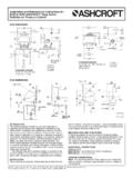
1 BULLETIN TH-1 Ashcroft Inc., 250 East Main Street, Stratford, CT 06614 USATel: 203-378-8281 Fax: 203-385-0408email: specifications are subject to change without notice. All sales subject to standard terms and conditions. Ashcroft Inc. 2012 09/12 BULLETIN TH-1 Ashcroft Inc., 250 East Main Street, Stratford, CT 06614 USATel: 203-378-8281 Fax: 203-385-0408email: specifications are subject to change without notice. All sales subject to standard terms and conditions. Ashcroft Inc. 2012 09/12 Eight Steps to Thermowell SelectionHow to OrderTYPICAL CODE 75W0750HT260C 75 W 0750 H T 260 C SIZE U-DIMENSION THREAD LAGGING SHANK TYPE BORE MATERIAL CAP & VARIATION FACING RATING SPECIAL CHAIN
2 LAGGING LENGTH CODE INCHES 50 1 2 75 3 4 10 1 12 11 4 15 11 2 20 2 30 3 40 4 CODE INCHES 0162 15/8 0250 21 2 0450 41 2 0750 71 2 1050 101 2 1350 131 2 1650 161 2 1950 191 2 2250 221 2 CODE LAGGING Without L With CODE INTERNAL THD.
3 1 2 NPSM 2 1 2 NPT CODE SHANK H Tapered S Straight R Stepped B Built-up CODE DIAMETER 260 .260 385 .385 CODE MATERIAL 1 Brass 2 St. St. CODE FACING F Flat R Raised J Ring-Joint L Lap-JointSEE NOTE2 CODE TYPE T NPT Thd. W Weld-In. F Flanged Van V Stone Socket- S Weld Limited M Space Threaded Ground G Joint C Sanitary CODE TYPE AA Brass Carbon B Steel C 304 S 316 CODE RATING # 150 150 300 300 600 600 1500 1500 2500 2500 SEE NOTES3 & 4 Note 1 Examplesa.
4 3 4 NPT 304 .260 Bore U 71 2 Tapered75W0750HT260Cb. Same as a. except Lagging (Standard Length)75W0750 LHT260Cc. Same as b. except Special Lagging = 31 2 75W0750 LHT260CL0350d. Same as a. except Tip Diameter (E) = .500 75W0750 LHT260 CXDQE500e. 11 2 300# Raised Face Flange 316 U = 101 2 .385 Bore Straight with Stainless Steel Cap & Chain,Standard Lagging Extension15W1050 LSF385S2R300 Note 2 For Special (Non-Standard) Lagging enter L _ _ _where _ _ _=Lagging Length in Inches x 100 Example 31 2 x 100 = L0350 Note 3 For Special Diameters Enter XDQ and write Identity and Value ofSpecial Diameter below Code, such as E =.
5 500 Note 4 Other X variations will be assigned for special designsNote 5 If U dimension is < 3 standard lag = 2 If U dimension is > 3 standard lag = 3 A Thermowell is highly recommendedfor use with temperature indicatingand control instrumentation to isolatethe temperature sensor from themedia being measured. A thermowellperforms an invaluable triple-dutyservice; Protects delicate instrument sens-ing elements against corrosive effects and resulting physicaldamage caused by media flow. Permits instrument interchange orcalibration check without disturb-ing or closing down the process. Helps to contain costly or danger-ous process fluids when properlyinstalled as an integral part of thevessel or for moreinformation.
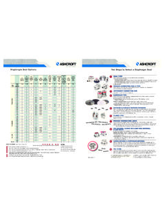
6 Or call us direct at800-328-8258 and let one of ourexperts help you specify the right Thermowell for your Steps to Thermowell +T U S Tip Dia. E Root Dia. B +T U S Tip Dia. E Root Dia. B PROCESS CONNECTION SIZEis the size of the portion of the Thermowell that connects with the vessel or pipe. This can be in the form of a thread size, flange size, pipe size, tri-clamp, LENGTHis commonly called the U dimension, this is that portion of the shank from the process connection (underside of the threads) to the tip of the shank which is inserted into the process area. For the most accurate reading it is recommended that the entire sensitive portion of the bulb be immersed in the EXTENSION & INSTALLATION WRENCH FLATSis shown as T on engineering drawings when applicable.
7 This is used when the vessel or pipe into which the Thermowell is inserted is insulated. This is the extra length between the process connection and the instrument connection of a thermo-well, which is determined by the insulation thickness. The standard lagging extensionis 3 (except for thermowells with a 2 U the T will be 2 ). Non standard extensionscan be supplied although, we suggest 3 increments to provide the proper insertion to match standard instrument stem CONFIGURATIONis the shape of that portion of a Thermowell that is inserted into the process. The tapered shank is recommended as opposed to a stepped or straight shank due to the superior strength and vibration CONNECTION TYPEis the portion of the Thermowell which provides the connection with the vessel or pipe.
8 These connections can be integral male threads, prepared surfaces for welding or brazing, flanges for mechanical pressure seals, the inside cylindrical diameter of a Thermowell which is sized to accommodate the stem or bulb of thermal instruments. This dimension can be critical as the toler-ance should provide easy installation of the instrument, but a snug fit to minimize thermal lag. Standard bore diameter is .260 or .385 .MATERIAL Selection is commonly based on corrosion resistance and strength. Selection should be compatible with process media, temperature and velocity as well as the material of the vessel or pipe to which it will be installed. INSTRUMENT INSERTION LENGTHis commonly called the S dimension, is actually a thermometer specification and not a Thermowell specification.
9 This is often given in Thermowell catalogs for is the length from the top of the mounting threads of a thermometer to the end of its stem. INTRODUCTIONA shcroft thermowells are available for light duty applications, high pressures, hightemperatures, or high velocity applications; as well as meeting many general serviceindustry needs. Selected on the basis of pressure, temperature, flow, vibration andcorrosion parameters, basic Thermowell types include: threaded, socket weld, weld in,flanged, sanitary and van stone. The threaded type is generally the least costly andmost versatile. Also available are custom thermowells for unique applications. Properthermowell Selection is critical to most applications.
10 To configure an Ashcroft Thermowell part number follow the Eight Steps . Typical S dimensions for threaded wellsWITHOUTSTANDARDLAGLAG U S T S 21 242641 263 971 29312101 212315131 215318161 218 191 2 324221 224 SPECIAL LAG EXAMPLES:21 245 941 26915 Threaded Tapered Well With Lagging ExternsionFlanged Well Raised FaceRing JointFlat FaceTHREADED WELLST apered shankshave a smaller diameter tip than the base of the well providing greater stiffness andquicker response time than a straight tapered shank is recommended due toits superior strength and vibration shankshave a significantly reduced tip diameter improving heat transfer to the sensing ele-ment.