Transcription of HPK-Series Asynchronous Servo Motors - …
1 Installation Instructions HPK-Series Asynchronous Servo Motors Catalog Numbers HPK-B1307, HPK-E1307, HPK-B1308, HPK-E1308, HPK-B1310, HPK-E1310, HPK-B1609, HPK-E1609, HPK-B1611, HPK-E1611, HPK-B1613, HPK-E1613, HPK-B1815, HPK-E1815, HPK-B2010, HPK-E2010, HPK-B2212C, HPK-E2212C, HPK-B2510C About This Publication This publication provides installation instructions for the HPK-Series Asynchronous Motors with a frame size of 1307 mm ( in.), 1600 mm ( in.), 1815 mm ( in.), 2010 mm ( in.), 2212 mm ( in.), or 2510 mm ( in.). Use this document if you are responsible for installing these Allen-Bradley Motors . Please read all instructions before installing this motor . Topic Page Important User Information 2 motor Catalog Number Identification 3 Before You Begin4 Installation and Maintenance Guidelines 4 Installing an HPK motor 11 Product Dimensions 15 motor Connectors 26 Load Force Capacities 27 Troubleshooting and Maintenance 29 Shaft Key Removal and Installation32 motor Cables and Accessory Kits 33 Specifications 33 Additional Resources 34 2 HPK-Series
2 Asynchronous Servo MotorsPublication HPK-IN001C-EN-P - June 2010 Important User InformationSolid state equipment has operational characteristics differing from those of electromechanical equipment. Safety Guidelines for the Application, Installation and Maintenance of Solid State Controls, publication , is available from your local Rockwell Automation sales office or online at It describes some important differences between solid state equipment and hard-wired electromechanical devices. Because of this difference, and also because of the wide variety of uses for solid state equipment, all persons responsible for applying this equipment must satisfy themselves that each intended application of this equipment is acceptable.
3 In no event will Rockwell Automation, Inc. be responsible or liable for indirect or consequential damages resulting from the use or application of this equipment. The examples and diagrams in this manual are included solely for illustrative purposes. Because of the many variables and requirements associated with any particular installation, Rockwell Automation, Inc. cannot assume responsibility or liability for actual use based on the examples and diagrams. No patent liability is assumed by Rockwell Automation, Inc. with respect to use of information, circuits, equipment, or software described in this manual. Reproduction of the contents of this manual, in whole or in part, without written permission of Rockwell Automation, Inc.
4 , is prohibited. Throughout this manual, when necessary, we use notes to make you aware of safety considerations. WARNING: Identifies information about practices or circumstances that can cause an explosion in a hazardous environment, which may lead to personal injury or death, property damage, or economic loss. ATTENTION: Identifies information about practices or circumstances that can lead to personal injury or death, property damage, or economic loss. Attentions help you to identify a hazard, avoid a hazard, and recognize the consequences. SHOCK HAZARD: Labels may be located on or inside the equipment, for example, a drive or motor , to alert people that dangerous voltage may be present.
5 BURN HAZARD: Labels may be located on or inside the equipment, for example, a drive or motor , to alert people that surfaces may be dangerous temperatures. IMPORTANTI dentifies information that is critical for successful application and understanding of the product. HPK-Series Asynchronous Servo Motors 3 Publication HPK-IN001C-EN-P - June 2010 motor Catalog Number Identification FACTORY DESIGNATED OPTIONS A= Standard MOUNTING TYPE/SHAFT KEY A= IEC Metric, Free Mounting Holes (Type FF), Foot and Flange Mount, Keyed Shaft B= IEC Metric, Free Mounting Holes (Type FF), Foot Mount Only, Keyed Shaft BRAKE 2= No Brake 4= ac Brake CONNECTORS 4= Right-angle RotatableBLOWER/JUNCTION BOX A= Inline Blower, F3 Jx BoxB= Top-mount Blower, F1 Jx BoxC= Top-mount Blower, F2 Jx BoxFEEDBACK M= Multi-turn High Resolution Encoder S= Single-turn High Resolution Encoder RATED SPEED (rpm) C= 1500 E= 3000 FRAME SIZE (mm)
6 1307 1308 1310 1609 1611 1613 1815 2010 2212 2510 VOLTAGE RATING B = 460V ac E = 400V ac BULLETIN HPK = Asynchronous Servo HPK - B 1307 C- S A 4 2 A A4 HPK-Series Asynchronous Servo MotorsPublication HPK-IN001C-EN-P - June 2010 Before You Begin Before unpacking the product, inspect the shipping carton for damage. If damage is visible, immediately contact the shipper and request assistance. Otherwise, proceed with unpacking. Remove the motor carefully from its shipping container, and visually inspect the motor for any damage. Carefully examine the motor frame, front output shaft, and mounting pilot for any defects.
7 Motors are shipped with wooden blocking to prevent axial movement of the shaft during shipment. Remove the blocking and bolts securing it and verify that the motor shaft turns freely. If motor is to be shipped or placed in long-term storage, blocking of the bearing is recommended. Keep the original packing material in case you need to return the product for repair or to transport it to another location. Use both the inner and outer packing cartons to provide adequate protection for a unit returned for service. Installation and Maintenance Guidelines The guidelines in this section provide you with information about installing Servo motor so it provides safe and reliable service.
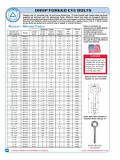
8 Handling Exercise care when lifting the motor . Always lift in the direction intended in the design of the lifting mechanism, and lift using all of the eyebolts or lifting lugs provided. The angle of lift formed by a lifting rope or chain must be greater than 45 degrees from horizontal. Diagrams are provided that show proper rigging and lift practices. ATTENTION: Do not attempt to open and modify the motor . Modifications that can be performed in the field are described in this manual; other changes should not be attempted. Only a qualified Allen-Bradley employee can service this type of motor . Failure to observe these safety procedures could result in personal injury or damage to : Eyebolts or lifting lugs are intended for lifting only the motor and factory mounted accessories.
9 Do not mount additional equipment before lifting and securing the motor . Failure to observe this precaution could result in bodily injury. HPK-Series Asynchronous Servo Motors 5 Publication HPK-IN001C-EN-P - June 2010 Take precautions during a lift to prevent hazardous overload due to deceleration, acceleration, or shock forces caused by abrupt raising or lowering, or swinging and twisting of a suspended motor . Lifting Guidelines For unusual conditions, such as side-wall and ceiling mounting of horizontal Motors and installation of vertical Motors shipped in a horizontal position, special precautions must be taken. We recommend that an experienced rigger be employed. To Prolong motor Life Thoughtful design and proper maintenance can increase the life of a Servo motor .
10 The following are guidelines to maximize the life of a Servo motor . Always provide a drip loop in a cable to reduce the potential for moisture related problems. A drip loop is a downward bend in the cable that lets water gather and drip off the cable rather than continue to flow along the cable. Avoid installing the motor with the shaft pointing upward. This orientation increases the risk of contaminant ingress. Environmentally-sealed connectors and cables are required to achieve an International Protection (IP) rating of IP54 for the motor . ATTENTION: Eyebolts may unscrew during lifting. Prior to lifting, check the eyebolts to verify that they are tight and attach lifting equipment to restrict turning during the lift.