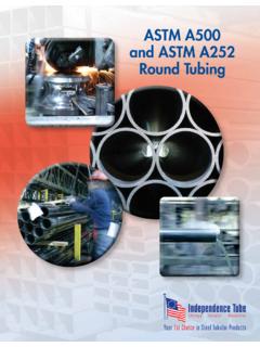
Transcription of HSSHollow Structural Sections - Independence Tube
1 HSSH ollow Structural SectionsHSS:TECHNICAL BROCHURE 2013 Steel Tube Institute2516 Waukegan Road, Suite 172 Glenview, IL 60025 T E L : 8 47. 4 01FA X : 8 47. 6 6 0 . 7 9 81 LRFD COLUMN LOAD TABLES2 The transformation of steel strip into hollow Structural Sections (HSS) is the result of a series of operations including forming, welding and sizing. Currently three methods are being used in North America for the manufacture of HSS. These methods are described below. Each method meets ASTM A-500 and CSA requirements for the the manufacture of HSS, and the sizes listed in this brochure may be produced to either Resistance Welding (ERW) Process In the tube mill, flat steel strip (1) is formed continuously around its longitudinal axis to produce a round tube. This is done by moving the strip through a progressive set of rolls (2-6). The strip edges (7) are heated by either high frequency induction or contact welding and then forged together by weld rolls to create a continuous longitudinal weld without the addition of filler metal.
2 The weld seam (8) is then cooled and processed through a set of sizing shaping rolls which cold-form it into a round (9), square (10) or rectangular (11) Weld-Square (ERW) ProcessIn the tube mill, flat steel strip (1) is formed continuously around its longitudinal axis to produce a round tube. This is done by moving the strip through a progressive set of rolls (2-6). The strip edges (7) are heated by either high frequency induction or contact welding and then forged together by weld rolls to create a continuous longitudinal weld without the addition of filler metal. The weld seam (8) is then cooled and processed through a set of sizing shaping rolls which cold-form it into a round (9), square (10) or rectangular (11) Arc Weld (SAW) ProcessIn the tube mill, flat steel strip (1) is formed continuously around its longitudinal axis to produce a round tube. This is done by moving the strip through a progressive set of rolls (2-6).
3 The strip edges (7) are heated by either high frequency induction or contact welding and then forged together by weld rolls to create a continuous longitudinal weld without the addition of filler metal. The weld seam (8) is then cooled and processed through a set of sizing shaping rolls which cold-form it into a round (9), square (10) or rectangular (11) Manufacturing Methods3 Load and Resistance Factor Design (LRFD) column load tables are presented for square, rectangular and round hollow Structural Sections (HSS) manufactured by the electric resistance welding (ERW ) method and for square, and rectangular HSS manufactured by the submerged arc welding (SAW ) method. Tables of design stresses for compression members for six minimum specified yield stress steels from Fy = 42 ksi to Fy = 70 ksi are also tabulated design strength loads and the compression member design stresses have been calculated in accordance with the AISC 2010 Specification for Structural Steel Revised section property data for HSS is published in hollow Structural Sections - Dimensions and section Properties available from the Steel Tube Institute of North for square and rectangular HSS are presented for Fy = 46 ksi and for Fy = 50 ksi.
4 Separate tables are used for HSS sizes produced by the ERW and SAW manufacturing for round HSS are presented for Fy = 42 ksi, Fy = 46 ksi and for Fy = 50 ksi. The round HSS are produced by the ERW manufacturing design strength loads have been calculated for effective lengths, KL, with respect to the least radius of gyration, r or ry, varying from 0 to 40 feet. A HSS defined as a slender element cross section , in accordance with Table of the AISC 2010 Specification for Structural Steel Buildings., is identified in the tables with an asterisk (*) immediately following the design wall thickness parameter in the tabulated values of compression member design stresses are calculated in accordance with the requirements of AISC Chapter E of the AISC 2010 Specification Note that these design stresses do not apply to a HSS defined as a slender element cross section .Refer to part 4, Design of Compression Members, of the AISC 14th Edition Steel Construction Manual for a discussion of the design strength of columns.
5 The symbols in these tables follow those used in the AISC Manual .ForewordTITLE IF NECESSARYNote: The information presented in this publication has been prepared in accordance with recognized engineering principles and is for general information only. While it is believed to be accurate, this information should not be used or relied upon for any specific application without competent professional examination and verification of its accuracy, suitability, and applicability by a licensed professional engineer, designer, or architect. The publication of the material contained herein is not intended as a representation or warranty on the part of The Steel Tube Institute of North America or of any other person named herein, that this information is suitable for any general or particular use or of freedom from infringement of any patent or patents. Anyone making use of this information assumes all liability arising from such must be exercised when relying upon other specifications and codes developed by other bodies and incorporated by reference herein since such material may be modified or amended from time to time subsequent to the printing of this edition.
6 The Institute bears no responsibility for such material other than to refer to it and incorporate it by reference at the time of the initial publication of this How to Use the Column Load TablesTable of Contents5 Design Stress Tables Square HSS (ERW) Fy = 46 ksi6 Square HSS (ERW) Fy = 50 ksi10 Round HSS (ERW) Fy = 42 ksi22 Round HSS (ERW) Fy = 46 ksi34 Round HSS (ERW) Fy = 50 ksi46 Rectangular HSS (ERW) Fy = 46 ksi58 Rectangular HSS (ERW) Fy = 50 ksi82 Square HSS (SAW) Fy = 46 ksi108 Square HSS (SAW) Fy = 50 ksi110 Rectangular HSS (SAW) Fy = 46 ksi 112 Rectangular HSS (SAW) Fy = 50 ksi 115 Column Load Tables Fy = 42 ksi118 Fy = 46 ksi119 Fy = 50 ksi120 Fy = 60 ksi121 Fy = 65 ksi122 Fy = 70 ksi1235 Example 1:Design the lightest 6-inch square ERW HSS column of Fy = 46 ksi (ASTM A500 Gr. B) to support a factored concentric load of 148 largest effective length, KL, is 16 the Fy = 46 ksi table for the 6-inch square ERW across the row at KL = 16 ft.
7 And note the following:6 x 6 x 5/8 is good for 286 kips > 148 kips - 1/2 is good for 245 kips > 148 kips - 3/8 is good for 195 kips > 148 kips - 5/16 is good for 167 kips > 148 kips - 1/4 is good for 138 kips < 148 kips - not goodSelect: 6 x 6 x 5/16 HSS (Weight = )Example 2:Design the lightest square ERW HSS column of Fy = 46 ksi (ASTM A500 Gr. B) to support a factored concentric load of 145 largest effective length, KL, is 12 the Fy = 46 ksi tables for square ERW across the rows at KL = 12 ft. and note the following:5 x 5 x 5/16 ( ) is good for 148 kips > 145 kips - 1/2 x 5 1/2 x 1/4 ( ) is good for 145 kips = 145 kips - x 6 x 1/4 ( ) is good for 168 kips > 145 kips - x 7 x 3/16 ( ) is good for 161 kips > 145 kips - x 8 x 3/16 ( ) is good for 179 kips > 145 kips - : 7 x 7 x 3/16 HSS (Weight = )HOW TO USE COLUMN TABLE LOADSE xample 3:Design the lightest 8-inch by 4-inch rectangular ERW HSS column of Fy = 50 ksi (ASTM A500 Gr.)
8 C) to support a factored concentric load of 170 effective length, KL, with respect to the minor axis is 14 feet. The effective length, KL, with respect to the major axis is 26 the Fy = 50 ksi table for the 8-inch x 4-inch rectangularEWR HSS. Read across the row at KL = 14 ft. and note the following:8 x 4 x 5/8 is good for 213 kips > 170 kips - 1/2 is good for 188 kips > 170 kips - 3/8 is good for 154 kips < 170 kips - not goodTentatively select: 8 x 4 x 1/2rx /ry = effective length for the major axis:26 / = the same table, read across the row at KL = and note the following:8 x 4 x 5/8 is good for 184 kips (interpolated) > 170 kipsrx /ry = - x 4 x 1/2 is good for 163 kips (interpolated) < 170 kips - not goodSelect: 8 x 4 x 5/8 HSS (Weight = )1 Nominal SizeWall ThicknessWeight Per FootDesign Wall ThicknessArea, In .2 1, In .4 r, I ective Length KL (ft)HSS/SQUARE (ERW) FOR LRFD COLUMNS Fy = 46ksiDesign Axial Strength in kips (ф = )
9 Fy=46ksi 16X16 1/2 3/8 5/16 * * 1170 782 572 1170 781 572 1169 781 572 1167 780 571 1165 779 571 1160 779 570 1160 777 569 1150 776 568 1140 774 567 1140 772 566 1140 769 564 1130 767 563 1120 764 561 1120 761 559 1110 758 557 1100 755 555 1090 751 553 1080 747 551 1070 743 549 1060 739 546 1050 735 543 1040 730 540 1030 725 537 1020 720 534 1010 714 531 994 709 528 981 703 524 968 697 520 955 691 517 941 684 513 927 677 509 913 670 504 899 663 500 884 656 495 870 647 491 855 640 486 840 631 481 825 623 476 809 614 470 794 606 465 1130 873 739 5/8 1/2 3/8 5/16 110 * * 1250 1020 748 551 1253 1017 747 550 1251 1015 747 550 1248 1013 745 549 1244 1010 744 548 1240 1010 743 547 1230 1000 741 546 1230 998 738 545 1220 992 736 543 1210 986 733 541 1210 980 729 539 1200 972 726 537 1190 965 722 535 1180 956 718 532 1170 947 713 529 1150 938 708
10 526 1140 928 703 523 1130 918 697 520 1110 907 691 516 1100 896 683 513 1090 884 674 509 1070 872 665 505 1050 859 656 500 1040 846 646 496 1020 833 636 491 1010 820 626 486 988 806 616 481 970 792 605 476 953 777 594 470 934 763 583 464 916 748 572 458 897 733 561 452 878 718 550 446 859 702 538 439 840 687 527 432 821 671 515 425 801 656 503 418 782 640 492 411 762 625 480 403 743 609 468 395 897 743 577 490 5/8 1/2 3/8 5/16 1/4 * * 1060 865 662 526 359 1062 864 661 525 359 1060 862 660 525 359 1056 859 658 524 358 1052 856 655 522 357 1050 852 652 521 356 1040 847 648 519 355 1030 841 644 517 354 1030 835 640 515 353 1020 828 634 512 351 1010 820 629 509 350 997 812 622 505 348 985 803 616 502 346 973 793 609 498 344 961 783 601 494 342 947 773 593 489 339 933