Transcription of HTZ-524 Rev. 2 Thermal Zone TZHSA, TZHSL, …
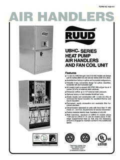
1 FORM NO. HTZ-524 REV. 2 Supersedes Form No. HTZ-524 Rev. 1 Manufactured forThermal Zone Philadelphia, PAAIR HANDLERSTZHLA- High Efficiency featuring R-22 RefrigerantTZHLL- High Efficiencyfeaturing Earth-FriendlyR-410A RefrigerantTZHSA- Standard Efficiencyfeaturing R-22 RefrigerantTZHSL- Standard Efficiencyfeaturing Earth-FriendlyR-410A RefrigerantFeatures TZHLA/TZHLL feature GE s new X-13 motor which pro-vides enhanced SEER performance with most ThermalZone Value Series outdoor units. 11/2ton [ kW] through 5 ton [ kW] models arebetween 421/2to 551/2inches [1080 to 1410 mm] tall and22 inches [559 mm] deep. Versatile 4-way convertible design for upflow, downflow,horizontal left and horizontal right applications. Factory-installed high efficiency indoor coil.
2 All models meet or exceed 330 to 400 CFM [156 to 189 L/s]per ton at .3 inches [.7 kPa] of external static pressure. Enhanced airflow up to .7" external static pressure. Sturdy construction with inch [.24 kPa] of reinforcedfoil faced jacket insulation for excellent Thermal andsound insulation. Field-installed auxiliary electric heater kits provide exactheat for indoor comfort. Kits include circuit breakers whichmeet UL and cUL requirements for service friendly refrigerantearth friendly refrigerant2 Engineering FeaturesGENERAL TERMS OF LIMITED WARRANTYT hermal Zone will furnish a replacement for any part of thisproduct which fails in normal use and service within theapplicable periods stated, in accordance with the terms ofthe limited Coil leaks caused byfactory (5) YearsElectric Heating (5) YearsAny Other (5) YearsFor Complete Details of the Limited Warranty, Including Applicable Terms and Conditions, See Your Local Installer orContact the Manufacturer for a Series The most compact unit design available, all standard heat airhandler models only 421/2 to 551/2inches [1079 to 1409 mm] high.
3 Attractive pre-painted cabinet exterior. Rugged wall steel cabinet construction, designed for addedstrength and versatility. " foil faced insulation mechanically retained in blowercompartment for excellent Thermal and sound performance. Four leg blower motor mount. Blower housing with controls, motor and blower. Slide outdesign for service and maintenance convenience. Traditional open wire element design for heat applications. Field convertible for vertical downflow, horizontal left hand orright hand air supply. 3 combustible floor base accessories fit all model sizes whenrequired for downflow installations on combustible floors. Indoor coil design provides low air side pressure drop, highperformance and extremely compact size. [ ] Designates Metric Conversions Expansion valve on indoor coil provides for operation with airconditioning or heat pump using the same coil.
4 Coils are constructed of aluminum fins bonded to internallygrooved copper tubing. Molded polymer corrosion resistant condensate drain pan isprovided on all indoor coils. Supply duct flanges provided as standard on air handler cabinet. Provisions for field electrical connections available from eitherside or top of the air handler cabinet. Connection point for high voltage wiring is inside the air handlercabinet. Low voltage connection is made on the outside of theair handler cabinet. Concentric knockouts are provided for power connection tocabinet. Installer may pull desired hole size up to 2 inches [51 mm] for 11/2 inch [38 mm] conduit. Front refrigerant and drain IdentificationTZHSA 1817J ADesign VariationA = 1st DesignVoltageA = 115/1/60J = 208/240/1/60 Cabinet Size17 = " [ mm] (600-1200 CFM)21 = 21" [ mm] (1200-1600 CFM)24 = " [ mm] (1600-1800 CFM)Capacity18 = 18,000 BTU/H [ kW]24 = 24,000 BTU/H [ kW]30 = 30,000 BTU/H [ kW]36 = 36,000 BTU/H [ kW]42 = 42,000 BTU/H [ kW]48 = 48,000 BTU/H [ kW]RefrigerantA = R-22L = R-410AS = Standard Model (PSC Motor)ClassificationH = Air HandlerThermal Zone [ ] Designates Metric ConversionsTZ HLA 24 17 JADesign VariationA = 1st DesignVoltageA = 115/1/60J = 208/240/1/60 Cabinet Size17 = " [ mm] (600-1200 CFM)21 = 21" [ mm] (1400-1600 CFM)24 = " [ mm] (1600-1800 CFM)
5 Capacity24 = 18,000/24,000 BTU/H [ kW]36 = 30,000/36,000 BTU/H [ kW]48 = 42,000/48,000 BTU/H [ kW]60 = 60,000 BTU/H [ kW]RefrigerantA = R-22L = R-410AL = High Efficiency (X-13 Motor)ClassificationH = Air HandlerThermal Zone Available Models at A VoltageTZHSA(L)-1817 AATZHSA(L)-2417 AATZHSA(L)-3017 AATZHSA(L)-3617 AATZHSA(L)-4221 AATZHSA(L)-4821 AATZHLA(L)-2417 AATZHLA(L)-3617 AATZHLA(L)-4821 AATZHLA(L)-4824 AATZHLA(L)-6024 AAAvailable Models at J VoltageTZHSA(L)-1817 JATZHSA(L)-2417 JATZHSA(L)-3017 JATZHSA(L)-3617 JATZHSA(L)-4221 JATZHSA(L)-4821 JATZHSA(L)-4824 JATZHLA(L)-2417 JATZHLA(L)-3617 JATZHLA(L)-4821 JATZHLA(L)-4824 JATZHLA(L)-6024JA Supply circuit protective devices may be fuses or HACR type circuit breakers. Largest motor load is included in single circuitand multiple circuit.
6 If non-standard fuse size is specified, use the nextlarger fuse size. J Voltage (230V) single-phase air handler isdesigned to be used with single or three phase230 volt power. In the case of connecting 3-phasepower to the air handler terminal block, bringonly two leads to the terminal block. Cap, insu-late and fully secure the third lead. The air handlers are shipped from the factory withthe proper indoor coil installed, and cannot beordered without a coil. The air handlers do not have an internal filterrack. An external filter rack or other means offiltration is CONNECTIONSMAY EXIT TOP OR EITHER SIDE HIGH VOLTAGE CONNECTION 7/8 [ mm],13/32 [ mm], 131/32 [50 mm] DIA. KNOCKOUTS. LOW VOLTAGE CONNECTION5/8 [ mm] AND 7/8 [ mm] KNOCKOUTVAPOR LINE CONNECTIONCOPPER (SWEAT)PRIMARY DRAIN CONNECTION3/4 [ mm] FEMALE PIPE THREAD (NPT)AUXILIARY DRAIN CONNECTION3/4 [ mm] FEMALE PIPE THREAD (NPT)UPFLOW/DOWNFLOW APPLICATION ONLYLIQUID LINE CONNECTIONCOPPER (SWEAT)AUXILIARY DRAIN CONNECTION3/4 [ mm] FEMALE PIPE THREAD (NPT)HORIZONTAL APPLICATION ONLYUPFLOW UNIT SHOWN:UNIT MAY BE INSTALLED UPFLOW, DOWNFLOW,HORIZONTAL RIGHT OR LEFT AIR.
7 24 CLEARANCE REQUIRED IN FRONT OF UNIT FOR FILTER AND COIL [495 mm]RETURN AIR OPENING 2111/16 [551 mm]105/16 [262 mm]SUPPLY AIRM odelCabinet SizeReturn AirOpening Width(Inches)Return Air OpeningDepth/Length(Inches)17157/8193/42 1193/8193/424227/8193/4 Return Air Opening DimensionsUnit Dimensions515/16 [151 mm]41/8 [105 mm]31/16 [76 mm]13/16 [48 mm]11/8 [29 mm]11/16 [27 mm]13/8 [35 mm]213/16 [71 mm]51/4 [133 mm]53/8 [136 mm]HORIZONTAL ADAPTER KIT(FACTORY INSTALLED ONLY ONMULTI-POSITIONED UNITS)VAPOR LINECONNECTIONAUXILIARY HORIZONTALDRAIN CONNECTIONPRIMARY DRAINCONNECTIONAUXILIARY UPFLOW/DOWNFLOWDRAIN CONNECTIONLIQUID LINECONNECTIONVERTICAL DRAIN PAN[ ] Designates Metric Conversions( ) Designates Unit with Double Coil CabinetNominal CoolingCapacityTonsSupplyDuct A In.
8 [mm]Air FlowCFM (Nom.) [L/s]Unit Weight/Shipping Weight (Lbs.) [kg]Unit WithCoil (Max. KW)LoHi1817 / 2417161/2[406]600 [283]800 [378]82/96 [37/44]3017 / 3617161/2[406]1000 [472]1200 [566]92/106 [37/48]3621191/2[495]1200 [566] 97/112 [44/51]4824231/2[584]1600 [755] 162/180 [73/81]6024231/2[584] 1800 [850]181/198 [82/90]UnitWidth W In. [mm]241/2[622]171/2[445]171/2[445]211/2[ 533]241/2[622]UnitHeight H In. [mm]551/2[1410]421/2[1080]421/2[1080]421 /2[1080]551/2[1410]211/2[533]501/2[1282] 4221 / 4821191/2[495]1400 [661]1600 [755]150/166 [68/75]Unit Dimensions & Weights5 UPFLOWDOWNFLOWA irflow DirectionsHORIZONTAL RIGHTHAND AIRFLOWHORIZONTAL LEFTHAND AIRFLOW6 Model Cabinet Size171721 Cooling BTUH x 1,000 Cooling Tons Pump or Air ConditioningMaximum Heat/Cool CFM [L/s]( CFM [18 L/s]/1,000 BTUH)(450 CFM [212 L/s]/Ton Nominal)675[319]900[425]1125[531]1350[63 7]1575[743]1800[850]1800[850]Heat Pump or Air ConditioningNominal Heat/Cool CFM [L/s]( CFM [16 L/s]/1,000 BTUH)(400 CFM [189 L/s]/Ton Nominal)600[283]800[378]1000[472]1200[56 6]1400[661]1600[755]1600[755]Heat Pump or Air ConditioningMinimum Heat/Cool CFM [L/s]( CFM [14 L/s]/1,255 BTUH)
9 (360 CFM [170 L/s]/Ton Nominal)540[255]720[340]900[425]1080[510 ]1260[595]1440[680]1440[680]Maximum kW Electric Heating& Minimum Electric Heat CFM [L/s]10500 [236]10650 [307]15865 [408]151015 [400]201200 [566]201400 [600]201400 [600]Maximum Electric Heat Rise F [ C]85 [29]85 [29]85 [29]85 [29]85 [29]85 [29]85 [29]24-06051930[911]1800[850]1620[765]25 1730 [821]85 [29]Airflow PerformanceAirflow performance data is based on cooling performancewith a coil and no filter in performance table forappropriate unit size, voltage and number of electric heaters tobe used. Make sure external static applied to unit allows opera-tion within the minimum and maximum limits shown in tablebelow for both cooling and electric heat operation. For optimumblower performance, operate the unit in the.
10 3 [8 mm] to .7inches [18 mm] external static range. Units with coilsshould be applied with a minimum of .1 inch [3 mm] static range. Airflow Operating Limits[ ] Designates Metric Conversions7 External Static Pressure Inches [kPa]PSC CFM [L/s] Air Delivery/RPM/Watts 240 VoltsRPM571 Blower Size/MotorHP [W]# of Speed626 MotorSpeedfromFactory687 ManufacturerRecommendedAir-Flow Range(Min/Max) CFMM otorSpeed736791 Watts171162157152146 10x61/5 HP [149]2 SpeedHighCFM 661 [312]612 [289]564 [266] [.02] [.05] [.07] [.10] [.12] [.15] [.17] 837878 RPM541596657706761 915 Watts180171166161109 10x61/5 HP [149]2 SpeedHigh 240V487/661 CFM[230/312 L/s]HighCFM 711 [336]662 [312]614 [290]LowCFM638 [301]607 [286]565 [267]530 [250]RPM 812853890487 [230] Watts 232216199 RPM616667715770808 Watts239230221206205 10x61/5 HP [149]2 SpeedHighCFM 888 [419]828 [391]774 [365]RPM 875908958 High 240V647/888 CFM[305/419 L/s]LowCFM817 [386]779 [368]757 [357]693 [327]647 [305] Watts 331313301 RPM646697745800838 Watts230221212197187 10x61/5 HP [149]2 SpeedHighCFM 838 [395]778 [367]724 [342]RPM 900933983 High 240V617/838 CFM[291/395 L/s]LowCFM787 [371]749 [353]727 [343]663 [313]617 [291] Watts 320302290 RPM700754794633870 Watts344313302309288 10x81/4 HP [186]