Transcription of HUB CITY BEVEL GEAR DRIVES Maintenance Instructions
1 HUB city BEVEL gear DRIVESACALL: (605)225-0360 FAX: (605)225-0567It is advisable to periodically inspect your BEVEL gear drive for any signsof impending service. Spare or replacement parts can often be orderedand obtained before disassembly is necessary, thus minimizing machinedown-time. The following symptoms can be inspected visually withoutdisassembly and may, in some cases, indicate extensive leaking from pinion housing, caps, cap screws or pipe plugs might be corrected by retightening or removal and recoating with pipesealant before tightening. If this does not correct the leaking condition,disassembly will be necessary to replace internal operating temperature (above 200 F.) could indicatethat unit was being overloaded and should be replaced entirely with alarger capacity unit.
2 Damaged bearings or inadequate oil level can alsocause heat leaking from seals indicates that shaft and/or seals are worn andneed replacing . Keep dirt and foreign particles off shafts in the area of theseals to minimize wear. Note: On initial run of new unit or after a newreplacement of seals, some lubricant leakage is normal for the first fewhours of running time until seals seat against the shafts. If conditionpersists, seal replacement will be end play of shafts if there is a noticeable (.005 or moremeasurable) shaft movement when couplings are removed and shaft ismoved back and forth, it is an indication of bearing wear. Removingshims between caps and gear case can usually correct the condition andavoid bearing backlash might indicate worn gears which often may bereadjusted, instead of the initial factory assembly, Loctite was used on the threads of all capscrews.
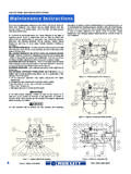
3 If any screws are removed, a new application of Loctite is nec-essary or lock washers must be installed. Note Screw threads andthreaded hole must be degreased before the application of Loctite .General Note These Instructions contain information common tomore than one model of BEVEL gear drive . To simplify reading,similar models have been grouped as follows:GROUP 1 Models 11, 150, 165, 175, 66 (illustrated), 65, 88, 600,800, 810, 850, 1000, 1010 and 2 Models 790, 920 (illustrated), 950, 1050 and 3 Models M2 and 4 Models AD1, AD2, AD3, AD4 & : For PINION SHAFT disassembly Instructions for Models1010 and 1200, follow the Group 2 Instructions . For PINIONSHAFT disassembly Instructions for the Model 790, follow theGroup 1 4 Group 1 DrivesFIGURE 3 Group 2 Drives9312826321724286311217258273351014 1515304313121116121730514294329131510319 1732331763112319201822237221 Maintenance InstructionsHUB city BEVEL gear DRIVESCALL: (605)225-0360 FAX.
4 (605)225-0567 BMaintenance InstructionsFor safe operation and to continue the unit warranty, when installing,reinstalling, or replacing a factory installed fastener for servicingpurposes, or to accommodate the mounting guards, shields or other lightload imposing devices, or for mounting the unit, it becomes theresponsibility of the customer or user to properly determine the quality,grade of fastener, thread engagement, load carrying capacity, tighteningtorque, and the means of torque PROCEDUREThe exterior threaded holes on this drive are for mounting the drive ordrive accessories (couplings, sprockets, etc.). They are not to be used forlifting the drive or any driver/driven certain that the power supply is disconnected before attempting toservice or install the unit, or remove any components.
5 Lock out the powersupply, and tag it to prevent unexpected application of protective clothing and eye shields when installing or maintainingunit and 1, 2 and 3 DRIVES (Refer to Figures 3 and 4 unless otherwisenoted.)1. Disconnect BEVEL gear drive from drive motor, couplings or drivenshafts to guard against personal injury. Remove all sprockets, orsheaves from BEVEL gear drive shafts with a puller tool to preventaccidental damaged to shafts. Remove all keys from Remove Pipe Plug (1) from bottom of gear Case (2) and drain alllubricant from unit, preferably while unit is , housing, and other components can reach high temperatures duringoperation, and can cause severe burns. Use extreme care when remov-ing lubrication plugs and vents while servicing the If old seals are to be salvaged, cover keyways with cellophane tape,plastic shim stock or paper.
6 Remove cap screws from Pinion Housing(3) and CAREFULLY remove Pinion Shaft Assembly (4). Be careful tokeep bearings clean and not to damage gear (5) Remove cap screws from Open Cap (6) which is opposite the gear sideof Cross Shaft Assembly (7, Figure 4) and Output Sleeve Assembly (8,Figure 3) and remove, being careful to keep bearings clean andpreventing damage to gear teeth. Slip open cap with seal off crossshaft or output Remove cap screws from Open Cap (9) on the gear side of gear Case(2) and remove cap and shims. This completes disassembly SHAFT DISASSEMBLYG roup 1 DRIVES Secure Pinion Shaft (10, Figure 4) with a vise, andremove Lock Nut (12) and washer from shaft. Place pinion assembly in apress with threaded end of shaft up and back side of BEVEL gear (5)supported.
7 Remove gear by pressing outer flange surface of Pinion Housing (3) on press anvil andpush threaded end of pinion shaft through housing, thereby removingInner Bearing Cone (14), Outer Bearing Cone (13) Spacer Washer (15),Seal (16) and Shaft (10) from pinion housing. Note disassembly of thepinion shaft from the housing will cause damage to the seal and seal mustbe replaced. If bearings are to be replaced, see Group 2 2 DRIVES Secure Pinion Shaft (10, Figure 3) with a vise, on shaftextension and remove cap screws from Seal Carrier (11), and remove itand gasket from Pinion Housing (3). Loosen Lock Nut (12) and removefrom pinion shaft. Remove remaining pinion assembly from the vise andplace inner flange surface of the Pinion Housing (3) on the anvil of apress. Push shaft through pinion housing, thereby releasing OuterBearing Cone (13).
8 Whenever gear set is changed, it is recommendedthat the Inner Bearing Cone (14) be replaced. If bearings are to bereplaced, remove Bearing Cups (15) from Pinion Housing (3) with a pullertool or if one is not available, gently tap opposite back sides of thebearing cups with a flat punch so that they are removed evenly and nodamage occurs to pinion 3 DRIVES (not illustrated) Disassembly of the pinion shaftassembly is essentially the same as Group 1 DRIVES above except a snapring must be removed instead of a lock nut so that BEVEL gear can beremoved. M2 and M3 DRIVES have ball bearings instead of taperedbearings and they may be removed easily from pinion housing after shafthas been pressed out. It is necessary to replace pinion housing seal dueto probable damage during disassembly SHAFT DISASSEMBLYG roup 1 DRIVES Cross Shaft Assembly (7, Figure 4) is disassembled byplacing Shaft (18) in a press with sleeve between anvil and 5 shows the use of a sleeve to support gear at hub.
9 On certaintypes of BEVEL gears it is recommended that this tool be used to protectgear teeth. This tool may be obtained from Hub city or machined for thepurpose in your shaft through Bearing Cone (19) and BEVEL gear (20). Invert shaftand rest Bearing Cone (21) on sleeve and anvil or, on some models, onSpacer (22) and push shaft through bearing cone. If bearings are to bereplaced, remove Bearing Cups (23) from Open Caps (6 and 9) with apuller tool or, if one is not available, gently tap opposite back sides of thebearing cups with a flat punch so that they are removed evenly and nodamage occurs to 5 Pressing Shaft out of Bearing and GearCAUTIONWARNINGWARNINGWARNINGWARNINGH UB city BEVEL gear DRIVESCALL: (605)225-0360 FAX: (605)225-0567 NOTE:All cross shafts in Group 1 DRIVES are shouldered.
10 Bearing Conesand Gears must ALWAYS be removed by moving them away from 3 DRIVES (not illustrated) Disassembly procedure for ModelsM2 and M3 cross shafts is similar to Group 1 above except that a spaceris located between the BEVEL gear and the bearing. The spacer isremoved with the gear . These models have ball bearings which areeasily removed from SLEEVE DISASSEMBLYG roup 2 DRIVES Bearing (24, Figure 3) is removed from Output Sleeve(25) on the side opposite the gear ( side) by placing inner bearingrace on the press anvil and pushing sleeve out of bearing. If Bearing (26)on the gear side needs to be replaced, it can be removed by tearing apartbearing and removing inner bearing race with a gear gear side Bearing (26) is to be salvaged and reused (because of areplacement of ring gear or output sleeve), it must be gently tapped offsleeve with a flat punch after drilling several opposing holes (max.)