Transcription of Hub City PowerTorque Shaft Mount Reducers
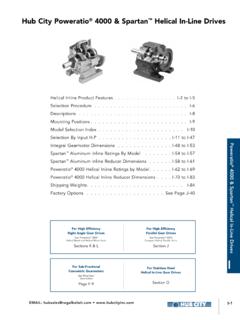
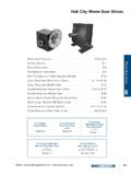
1 Hub City PowerTorque Shaft Mount Reducers PowerTorque Features and Description .. G-2. Nomenclature .. G-4. Selection Instructions .. G-5. Selection By Horsepower .. G-7. PowerTorque Shaft Mount Reducers Mechanical Ratings .. G-12. Dimensions .. G-14. Accessories .. G-15. Screw Conveyor Accessories .. G-22. For Additional Models of Shaft Mount Reducers G. See Sections F & J. EMAIL: G-1. Hub City PowerTorque Shaft Mount Reducers Ten models available from 1/4 HP through 200 HP capacity manufacturing Quality Manufactured to the highest quality standards in the industry, assembled using precision manufactured components made from top quality materials Designed for the toughest applications in the industry Efficiency per Housings Gear Stage! High strength ductile iron housings, rather than cast iron material Gearing High Efficiency gearing is manufactured from 8620 steel, case carburized, hardened to RC62, and precision ground, AGMA Class 11, rather than crowned and shaved Output Bores Standard bores range from 1-7/16 through 5-7/16.
2 Ratios Ratios from 9:1, 15:1 and 25:1. Shafts Lubrication Input shafts are machined from high strength Ample lubrication is provided by abundant alloy steel and hardened for premium load splash from the large oil sump carrying capability Interchangeablity Bearings Dimensionally and mechanically interchange- Tapered roller bearings are selected for able with most major brands optimum life and load carrying capability Warranty Seals Backed by an 18 month warranty for assured Double lip seals feature metal reinforcement dependable longevity while providing trouble and ride on precision ground Shaft surfaces for free service longevity G-2 CALL: ( 605 ) 225-0360 FAX: ( 605 ) 225-0567. Hub City PowerTorque Shaft Mount Reducers The Hub City Advantage Hub City PowerTorque Accessories complete the drive package by providing tapered bushings, backstops, and motor mounts.
3 Screw conveyor drive accessories include adapter flanges and drive shafts. Tapered Bushing Kits Flanged bushing Mount Removal screws allow for easy demounting Ductile iron material for shock resistance Clamp fit, no setscrews Split design eliminates seizing problems Backstop Assemblies Quick installation on input Shaft Internally installed, sealed from contamination Lubricated by internal gear lubricant PowerTorque Shaft Mount Reducers Designed to operate in either direction Motor Mounts All-Steel construction for rigidity Compact design eliminates need for motor base Top plate adjusts for easy tensioning of drive belt Mounting holes provided match NEMA standards Screw Conveyor Adapter Flanges Conform to CEMA standards Bolt-on design allows easy mounting Open center for contaminate dropout Screw Conveyor Drive Shafts G. Machined from high strength alloy steel Conform to CEMA dimensional standards Easy installation into standard hollow bore Belt Guards All-Steel construction Adjustable to fit a wide range of sheaves and motor frames Designed for easy installation, no drilling required EMAIL: G-3.
4 Hub City PowerTorque Shaft Mount Reducers Description Descriptions For Ordering Shaft Mount Reducers Model Maximum Output Bore Input Configuration Ratio PT22 115 S 25. PowerTorque . Shaft Mount reducer Nominal Ratio 09 : 9/1. 15 : 15/1. Unit Size 25 : 25/1. 1. 2. 3 Input Configuration 4 S : Shaft Input 5. 6. 7 AGMA Maximum 8 Output Bore 9 107 : 1-7/16. 10 115 : 1-15/16 . 203 : 2-3/16 . 207 : 2-7/16 . 215 : 2-15/16 . 307 : 3-7/16 . 315 : 3-15/16 . 407 : 4-7/16 . 415 : 4-15/16 . 507 : 5-7/16 . Part Number Prefixes 0270-XXXXX Standard Assembly 0271-XXXXX Modified Assembly 0273-XXXXX Standard Service Part 0275-XXXXX Modified Service Part 0279-XXXXX Accessory Kit G-4 CALL: ( 605 ) 225-0360 FAX: ( 605 ) 225-0567. Hub City PowerTorque Shaft Mount Reducers Selection Procedure Hub City PowerTorque Reducers are selected on the put speeds to 200 RPM and ratings up to 200 HP.
5 The basis of input horsepower and output speed. There selection tables have been established so that once are ten double reduction PowerTorque Models avail- the horsepower and driven speed are known the appro- able in nominal ratios of 9:1, 15:1, and 25:1 with out- priate model can be readily selected. AGMA Load Classification Numbers Determine the AGMA Load Classification Number the reducer ratings for the stresses created by different for your application from the AGMA tables in the types of loads. The AGMA Load Classes provide for a Engineering Manual. In mechanical drives the presence momentary or starting load of times for Class I, of shock loads will usually reduce the life of the Reducers . for Class II, and for Class III. Refer to the AGMA. In order to provide optimum service in heavily loaded tables in the Engineering Manual for further information applications, it is necessary to use load classes to adjust and cautions on the selection of proper service factors.
6 UP TO 3 HRS. 3 TO 10 HRS. OVER 10 HRS. LOAD CLASS TOTAL OPERATION TOTAL OPERATION TOTAL OPERATION. PowerTorque Shaft Mount Reducers ( ) PER DAY PER DAY PER DAY. I Moderate Uniform ( ) Shock Load Load II Heavy Moderate Uniform ( ) Shock Load Shock Load Load III Heavy Moderate ( ) Shock Load Shock Load Select reducer Size and Ratio Refer to the applicable Selection Table for the AGMA required HP and Output Speed, and read across to find Load Class I, II, or III on pages G-7 to G-11. Locate the the reducer size. Select Tapered Bushings Compare the hollow Shaft bore with the diameter of the If the driven Shaft diameter is larger than the maximum driven Shaft . If the driven Shaft is smaller than the maxi- bore for the reducer selected, it is necessary to either mum bore for the reducer selected, select the proper turn down the driven Shaft , or select a larger reducer .
7 Tapered bushings from the table on page G-15 to adapt the hollow Shaft bore to the diameter of the driven Shaft . Select Sheave Ratio G. To determine the V-belt sheave ratio required to Refer to the catalog of your chosen V-belt supplier to produce the desired output speed, use the following select the most economical V-belt drive to transmit the formula: sheave ratio = exact motor RPM / (output RPM HP at the required output speed by following the selec- X exact gear ratio). tion procedure outlined in the V-belt catalog. EMAIL: G-5. Hub City PowerTorque Shaft Mount Reducers Selection Procedure CAUTION CAUTION. Refer to the Minimum Diameter for Driven Sheaves listed Backstops are not recommended for applications in the Selection Tables to be certain that your driven involving energy absorption and shock or torque sheave selection is larger than the minimum diameter loads in excess of reducer ratings or on applications recommended for the reducer selected.
8 Such as chair lifts, amusement rides, etc. where the safety of a person or property is dependent on their Accessories: function. On such applications, other safety devices should be provided. Select Motor Mount Select the motor frame and motor Mount size from the Backstops are designed to prevent rotation not more tables on page G-16 to G-19 based on the reducer size. than five times in an 8 hour period with a minimum of one minute in the over-running direction between each Select Belt Guards engagement. If reversing operation is more frequent or over-running time is less, the application should be Select belt guards from the tables on pages G-20 and referred to the factory. G-21 based on the reducer size. Select Screw Conveyor Drive Shaft and CAUTION. Adapter Select the CEMA adapter and drive Shaft from the tables Lubricants with extreme pressure (EP) additives should on page G-22 based on the reducer size.
9 Not be used in units with backstops installed. Select Backstop Other Accessories Supplied Upon Optional backstops are available for applications that Request: require the prevention of reverse rotation. Select the Cooling Fans backstop from the table on page G-15 based on the Mounting Brackets reducer size. Backstops are installed on the high speed Auxiliary Seal Kits pinion Shaft by removing the cover on the back side (opposite side from the input Shaft extension) of the Note: A torque-arm assembly is supplied with all Shaft Mount Reducers . housing. For Lubrication and Installation Instructions Refer to Section S. G-6 CALL: ( 605 ) 225-0360 FAX: ( 605 ) 225-0567. Hub City PowerTorque Shaft Mount Reducers Selection By Input Horsepower Class I Service OUTPUT reducer MINIMUM OUTPUT reducer MINIMUM. HP RPM SELECTION SHEAVE DIA. HP RPM SELECTION SHEAVE DIA.
10 4 ~ 70 PT21107-25 PT21107-15 7~9 PT26307-25 71 ~ 85 PT21107-25 PT21107-15 10 ~ 17 PT25215-25 86 ~ 115 PT21107-15 PT21107-09 18 ~ 26 PT24207-25 PT24207-15 116 ~ 140 PT21107-15 PT21107-09 27 ~ 46 PT23203-25 PT23203-15 141 ~ 200 PT21107-09 5 47 ~ 70 PT22115-25 PT22115-15 5 ~ 70 PT21107-25 PT21107-15 (con't.) 71 ~ 85 PT22115-25 PT22115-15 71 ~ 85 PT21107-25 PT21107-15 86 ~ 92 PT21107-09 PT22115-15 86 ~ 115 PT21107-15 PT21107-09 93 ~ 115 PT21107-15 PT21107-09 116 ~ 140 PT21107-15 PT21107-09 116 ~ 140 PT21107-15 PT21107-09 141 ~ 200 PT21107-09 141 ~ 200 PT21107-09 4~6 PT22115-25 4~6 PT28407-25 7 ~ 70 PT21107-25 PT21107-15 7~9 PT27315-25 71 ~ 85 PT21107-25 PT21107-15 10 ~ 15 PT26307-25 86 ~ 115 PT21107-15 PT21107-09 16 ~ 26 PT25215-25 116 ~ 140 PT21107-15 PT21107-09 27 ~ 40 PT24207-25 PT24207-15 141 ~ 200 PT21107-09 41 ~ 70 PT23203-25 PT23203-15 PowerTorque Shaft Mount Reducers 4~5 PT23203-25 71 ~ 74 PT23203-25 PT23203-15 6 ~ 10 PT22115-25 75 ~ 85 PT22115-25 PT22115-15 11 ~ 70 PT21107-25 PT21107-15 86 ~ 95 PT22115-15 71 ~ 85 PT21107-25 PT21107-15 96 ~ 140 PT22115-15 86 ~ 115 PT21107-15 PT21107-09 141 ~ 200 PT22115-09 116 ~ 140 PT21107-15