Transcription of hubs switches routers - Router Alley
1 hubs vs. switches vs. routers Aaron Balchunas * * * All original material copyright 2014 by Aaron Balchunas unless otherwise noted. All other material copyright of their respective owners. This material may be copied and used freely, but may not be altered or sold without the expressed written consent of the owner of the above copyright. Updated material may be found at 1- hubs vs. switches vs. routers - Layered Communication Network communication models are generally organized into layers. The OSI model specifically consists of seven layers, with each layer representing a specific networking function.
2 These functions are controlled by protocols, which govern end-to-end communication between devices. As data is passed from the user application down the virtual layers of the OSI model, each of the lower layers adds a header (and sometimes a trailer) containing protocol information specific to that layer. These headers are called Protocol Data Units (PDUs), and the process of adding these headers is referred to as encapsulation. The PDU of each lower layer is identified with a unique term: # Layer PDU Name 7 Application - 6 Presentation - 5 Session - 4 Transport Segments 3 Network Packets 2 Data-link Frames 1 Physical Bits Commonly, network devices are identified by the OSI layer they operate at (or, more specifically, what header or PDU the device processes).
3 For example, switches are generally identified as Layer-2 devices, as switches process information stored in the Data-Link header of a frame (such as MAC addresses in Ethernet). Similarly, routers are identified as Layer-3 devices, as routers process logical addressing information in the Network header of a packet (such as IP addresses). However, the strict definitions of the terms switch and Router have blurred over time, which can result in confusion. For example, the term switch can now refer to devices that operate at layers higher than Layer-2.
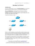
4 This will be explained in greater detail in this guide. hubs vs. switches vs. routers Aaron Balchunas * * * All original material copyright 2014 by Aaron Balchunas unless otherwise noted. All other material copyright of their respective owners. This material may be copied and used freely, but may not be altered or sold without the expressed written consent of the owner of the above copyright. Updated material may be found at 2 Icons for Network Devices The following icons will be used to represent network devices for all guides on : RouterHub____Switch___Multilayer Switch hubs vs.
5 switches vs. routers Aaron Balchunas * * * All original material copyright 2014 by Aaron Balchunas unless otherwise noted. All other material copyright of their respective owners. This material may be copied and used freely, but may not be altered or sold without the expressed written consent of the owner of the above copyright. Updated material may be found at 3 Layer-1 hubs hubs are Layer-1 devices that physically connect network devices together for communication. hubs can also be referred to as repeaters.
6 hubs provide no intelligent forwarding whatsoever. hubs are incapable of processing either Layer-2 or Layer-3 information, and thus cannot make decisions based on hardware or logical addressing. Thus, hubs will always forward every frame out every port, excluding the port originating the frame. hubs do not differentiate between frame types, and thus will always forward unicasts, multicasts, and broadcasts out every port but the originating port. Ethernet hubs operate at half-duplex, which allows a host to either transmit or receive data, but not simultaneously.
7 Half-duplex Ethernet utilizes Carrier Sense Multiple Access with Collision Detect (CSMA/CD) to control media access. Carrier sense specifies that a host will monitor the physical link, to determine whether a carrier (or signal) is currently being transmitted. The host will only transmit a frame if the link is idle. If two hosts transmit a frame simultaneously, a collision will occur. This renders the collided frames unreadable. Once a collision is detected, both hosts will send a 32-bit jam sequence to ensure all transmitting hosts are aware of the collision.
8 The collided frames are also discarded. Both devices will then wait a random amount of time before resending their respective frames, to reduce the likelihood of another collision. Remember, if any two devices connected to a hub send a frame simultaneously, a collision will occur. Thus, all ports on a hub belong to the same collision domain. A collision domain is simply defined as any physical segment where a collision can occur. Multiple hubs that are uplinked together still all belong to one collision domain. Increasing the number of host devices in a single collision domain will increase the number of collisions, which will degrade performance.
9 hubs also belong to only one broadcast domain a hub will forward both broadcasts and multicasts out every port but the originating port. A broadcast domain is a logical segmentation of a network, dictating how far a broadcast (or multicast) frame can propagate. Only a Layer-3 device, such as a Router , can separate broadcast domains. hubs vs. switches vs. routers Aaron Balchunas * * * All original material copyright 2014 by Aaron Balchunas unless otherwise noted. All other material copyright of their respective owners.
10 This material may be copied and used freely, but may not be altered or sold without the expressed written consent of the owner of the above copyright. Updated material may be found at 4 Layer-2 Switching Layer-2 devices build hardware address tables, which at a minimum contain the following: Hardware addresses for hosts The port each hardware address is associated with Using this information, Layer-2 devices will make intelligent forwarding decisions based on the frame (or data-link) headers. A frame can then be forwarded out only the appropriate destination port, instead of all ports.