Transcription of Hydraulic Considerations in Pumping System Design
1 VWEA16_Rogers_Hydraulic Considerations in Pumping System DesignHydraulic Considerations in Pumping System DesignVWEA Wastewater Operations Education ConferenceRoanoke VirginiaJuly 14, 2016 VWEA16_Rogers_Hydraulic Considerations in Pumping System DesignAgenda Basics of Hydraulics and Pump Operation Pumping System Design Process Types of Pumps System Curve Development Pump Station Layout Pump Selection Considerations Hydraulic Concerns Case Studies Summary QuestionsVWEA16_Rogers_Hydraulic Considerations in Pumping System DesignAbbreviations and Acronyms BEP best efficiency point BHP brake horsepower fps or ft/sec feet per second (velocity) FM force main gpm gallons per minute (flow) H Head (feet) HP horsepower n rotational speed NPSHA net positive suction head available NPSHR net positive suction head required psi pounds per square inch (pressure) Q Flow Rate (gpm, mgd, ) rpm revolutions per minute TDH total dynamic head3 VWEA16_Rogers_Hydraulic Considerations in Pumping System DesignBasics of Pump Operation A pump lifts fluid from one elevation to another Work is needed to lift fluid Work is independent of type Human Power Animal Power Wind Power Steam Power Electrical Power Pump can lift continuously or in increments Take-away.
2 Higher lift requires more work Higher flow requires more work Faster work requires more powerVWEA16_Rogers_Hydraulic Considerations in Pumping System Design Pumps deliver fluid against pressure Pressure = Force / Area (psi) Head (feet) is commonly used to express pump operating pressure A foot high column of water exerts a pressure equal to 1 psi Car tires ~ 35 psi = 81 feet of headVWEA16_Rogers_Hydraulic Considerations in Pumping System DesignClosed Conduit Flow (Q) Volume of fluid passing per time (gpm, mgd, ) Q (cfs) = Area (ft2) x Velocity (fps) For a given flow, the smaller the conduit the larger the velocity. Higher velocity translates into increased frictional headlossVWEA16_Rogers_Hydraulic Considerations in Pumping System Design TDH is the total amount of head a pump must operate against to deliver wastewater to a desired location TDH = Static Head + Head Loss (HL) Static Head exists when pump is on or off Head Loss exists only when fluid is pumpedVWEA16_Rogers_Hydraulic Considerations in Pumping System DesignFor free surfaces.
3 Static Head = Discharge Tank WSEL Suction Tank WSEL Static Discharge Head = Discharge Tank WSEL Pump CL Static Suction Head = Suction Tank WSEL Pump CLSuction Lift Negative Suction HeadFlooded Suction Positive Suction HeadVWEA16_Rogers_Hydraulic Considerations in Pumping System Design Energy dissipated due to friction and turbulence during pump operation Major Losses (Friction Losses) Due to friction between pumped water and inner surface of piping Hf= L (V/Ch) (Hazen-Williams Formula) where: L is length of pipe (feet) D is diameter of pipe (square feet) V is mean velocity (fps) Chis Hazen-Williams friction coefficient (new up to 140 and old as low as 80) Minor Losses Due to turbulence at bends, fittings, valves, etc. Hf= K (V2/2G) (Headlossfactor times velocity head)VWEA16_Rogers_Hydraulic Considerations in Pumping System Design NPSHA= Atmos. Head + Static Suction Head Suction HL Standard atmospheric pressure = psi (34 ft.)
4 Head) Net Positive Suction Head Required (NPSHR) Furnished by pump manufacturer pump specific Increases with pump flow NPSHA< NPSHR Cavitation Typically occurs in systems with static lift Could occur in flooded suction scenario with extremely long lengths of suction piping Insufficient submergence can lead to vortexingVWEA16_Rogers_Hydraulic Considerations in Pumping System Design Work A force does work when it acts on a body over a distance Units of foot pound (ft-lb) Wastewater pumps do work to move the wastewater Power Rate of work done (ft-lb/s) Wastewater pumps most often do work by using electric motors Motors are commonly rated by horsepower (hp) 1 unit of hp is equal to 550 ft-lbs/sVWEA16_Rogers_Hydraulic Considerations in Pumping System DesignThe Pumping System Design Process Collect information Determine type of pump to be used Develop station layout Develop System curves Select pumps that match the System curves Write your specification Coordinate Finalize the design12 VWEA16_Rogers_Hydraulic Considerations in Pumping System DesignCollect Information What type of fluid is to be pumped?
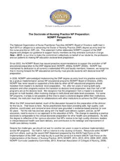
5 Fluid properties: density, viscosity, solids content, temperature From where to where? System characteristics: friction and minor losses, suction lift, static head, other pumps operating simultaneously How much what are Design flowrates?13 VWEA16_Rogers_Hydraulic Considerations in Pumping System DesignDetermine Type of Pump Flow and head requirements Type of fluid, solids content Site conditions Footprint and headroom constraints Subgradeconditions Elevation constraints Suction and discharge inverts Suction head availableMore than one type may work -what s best for the specific application and owner preference?14 Fairbanks-MorseVWEA16_Rogers_Hydraulic Considerations in Pumping System DesignPeripheral/RegenerativePumpsJetGas liftHydraulic ramElectromagneticPositiveDisplacementKi neticCentrifugalSpecialSingle suctionDouble suctionRadial FlowMixed FlowSelf-primingNon-self-primingAxial FlowPistonPlungerDiaphragmReciprocatingR otaryVaneScrewGearPistonLobeHoseOpen impellerSemi-open impellerClosed impellerHydraulic InstituteTypes of PumpsPump Types15 VWEA16_Rogers_Hydraulic Considerations in Pumping System DesignTypes of Pumps Kinetic (Rotodynamic) Pumps Energy is imparted to the fluid by a rotating impeller which increases the flow velocity and converts to a pressure increase upon exit.
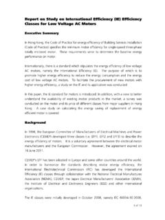
6 Can be safely operated under closed valve conditions (for short periods of time). Three Types: Radial-flow pumps (Centrifugal Pump) -higher pressures and lower flow rates than axial-flow pumps. Axial-flow pumps -lower pressures and higher flow rates than radial-flow pumps. Mixed-flow pumps A compromise between radial and axial-flow pumps -operate at higher pressures than axial-flow pumps while delivering higher discharges than radial-flow pumps. Positive Displacement (PD) Pumps PD pumps physically displace fluid Closing a valve downstream can lead to continual pressure build up and failure of pipelineVWEA16_Rogers_Hydraulic Considerations in Pumping System DesignPositive Displacement PumpsHP Reciprocating Triplex PumpLobe PumpHose PumpProgressing Cavity PumpVWEA16_Rogers_Hydraulic Considerations in Pumping System DesignProgressing Cavity Pumps Flowrate fixed to speed Capable of Pumping highly viscous stream Commonly used in sludge and slurry Pumping applications Operates at high pressures Must avoid running pump dry Provide safety features on dischargeVWEA16_Rogers_Hydraulic Considerations in Pumping System DesignCentrifugal PumpA centrifugal pump lifts fluid from one elevation to another by continuously adding kinetic energy (accelerating the fluid)
7 Using a rotating impellerVWEA16_Rogers_Hydraulic Considerations in Pumping System DesignCommon Types of Centrifugal Pumps for Water and Wastewater Horizontal Split Case Pumps Vertical Turbine Pumps End Suction Pumps Closed impeller Non-Clog pumps Submersible non-clog pumps20 VWEA16_Rogers_Hydraulic Considerations in Pumping System Design Water treatment: Raw Water High service Pumping Transfer Pumping Wastewater treatment: Reuse filter feed Reuse distribution Treated effluent pumpsHorizontal Split CaseCharacteristics Wide flow range Heads to ~500 ft. for single stage, higher for two-stage High efficiency (85-95%) Ease of maintenance Flat curveHorizontalVertical Horizontal motor Vertical motor Single or two stage Dual diesel / electric driveConfigurationsApplicationsVWEA16_Ro gers_Hydraulic Considerations in Pumping System Design Wide flow range Wide head range addstages for higher head Steep curve Very compact footprint Prone to vibration Difficult to serviceVertical Turbine Can-type Wetwell-mounted Submersible22 Water treatment: Raw water pumps Groundwater pumps (submersible) Membrane feed pump Filter backwash pump High service pumps Transfer pumps Wastewater treatment.
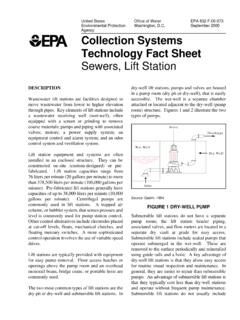
8 Reuse filter feed Reuse distribution pumps Treated effluent pumps VTSH (vertical turbine solids-handling) CharacteristicsApplicationsConfiguration sVWEA16_Rogers_Hydraulic Considerations in Pumping System DesignEnd Suction Low to Medium flow High head -add stages Curve shape varies Vertical -save space or to mount motor above flood elevation Horizontal -provides good access and saves head room Close-coupled (single pump/motor shaft) Direct coupled (motor shaft connected to the pump shaft by a shaft coupling) V-belt drive Extended shaft Submersible Water treatment: Booster Pumping Filter Backwash Membrane Feed Chemical Feed Raw water Wastewater treatment (non-clog impellers): Sewage lift stations Raw sewage pumpsCharacteristicsApplicationsConfigur ationsVWEA16_Rogers_Hydraulic Considerations in Pumping System DesignEnd Suction Pumps Wastewater24 Heads to ~250 ft. for a single stage Best efficiencies 70-75% Impeller options:Vortex Impeller(recessed impeller)Channel Impeller(enclosed, 1-3 vanes)Semi-Open ImpellerHydraulic efficiency increasesSolids handling performance improvesSewage lift stationtypical applicationGrit and sludge pumpingtypical applicationsVWEA16_Rogers_Hydraulic Considerations in Pumping System DesignPump Type Selection Example Griffith RWPS Had available land area and suction head Rock subgrade Suitable curve shape Owner preference Ease of maintenance25 Selected horizontal split-case pumps why?
9 VWEA16_Rogers_Hydraulic Considerations in Pumping System DesignCentrifugal Pump Summary Larger impellers -Greater flow and head Greater Speed Greater flow and head Larger, slower impellers are more efficient but cost more Pumps in parallel -more flow at same head Pumps in series -higher head at same flow Generally, power increases as flow increases to run out Best efficiency point (BEP) is at max of efficiency curveVWEA16_Rogers_Hydraulic Considerations in Pumping System DesignCentrifugal Pumps -Points to Watch Rotational speeds 1,800 rpm Non-clog in particular Flooded suction -no priming needed Curve shall continually rise to shut off Steeper pump curves are best for VFDs Duty point to be ~75% Qmax, close to BEP Aim for efficiencies > 75% single stage Size motor HP for run out or maximum power NOT duty pointVWEA16_Rogers_Hydraulic Considerations in Pumping System DesignStation Layout -Where to Start?
10 Resources Hydraulic Institute (HI) Standards, other references Consider constraints site, budget, etc. Collect/develop information needed to create System curves Elevations of suction, pump room floor, high points, discharge For retrofits, survey/measure existing elevations, test existing pumps for flow and pressure Develop piping System layout, list of minor losses28 VWEA16_Rogers_Hydraulic Considerations in Pumping System DesignStation Layout Considerations Provide sufficient work space between pumps Use largest pump and motor dimensions (now or future) Allow for expansion Think through process of installing/removing pumps and valves Size crane and openings for heaviest / largest single item in the station Ensure crane can reach everything it needs to lift Consider need for portable hoists or truck access, etc. when selecting pump spacing, sizing hallways Involve operations and maintenance staff early29 VWEA16_Rogers_Hydraulic Considerations in Pumping System DesignLayout - Hydraulic Institute Standards American National Design Standards for Pump Intake and Centrifugal Pumps Wetwells-different designs for clear and solids-bearing liquids Provide steady, uniform flow with minimal flow disturbances Keep solids entrained Piped intakes recommended piping configurations.