Transcription of HYDRAULIC CONTROLLERS UC4, UC4M, UC4MR
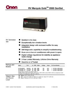
1 1728 Orbit Way - Minden, Nevada 89423 P: 775-782-1700 F: 775-782-1701 35 \\SERVER\CATALOG 2018\2018 Catalog Rev 1 Jack Tank Pump DL D B A BPS R Jack Tank Pump A BPS R DL D B Specifications Standard Features *Maximum Flow** 185 gpm (700 I/min) Operating Pressure Minimum 50 psi ( bar) Maximum 800 psi (55 bar) Note: Consult factory when applications exceed pressure ratio over to 1, example (Max. / Min. :280 / 100 ) Line Connections Jack, Tank Port 2 NPT Pump Port (flange) 2 NPT or Grooved Gauge Ports Pump Pressure: A Port (1/8 NPT) System pressure: B Port (1/8 NPT) Pressure Switch: S Port (1/8 NPT) Operating Temperature 80 150 F (26 65 C) Oil Type Hyd.
2 ISO VG 32 150 SUS @ 100 F (38 C) Solenoid Coils Encapsulated CSA / UL Listed Overall Dimensions Width 8 7/16 inches (214mm) Height 10 1/2 inches (268mm) Depth 9 3/16 inches (233mm) Weight 27 lbs. ( ) *Refer to flow Charts ( ) ** To insure proper valve selection please return a completed copy of our Job Specification Sheet (pg. 3) to Maxton. Unit body construction. Steel sleeve inserts in valve body. Feedback control for stall free operation.
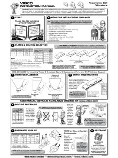
3 Individualized adjustments. Integrated relief valve. High efficiency solenoids. 115 VAC / 24 VDC solenoid coils. Factory tested prior to shipping. 2 year limited warranty. Optional Features Explosion Proof Coil Cover Thread to Grooved Adapters (2 ) Low Pressure Switch Tank Discharge Filter 1/8 or 1/4 Ball Valves Quick Disconnect Coupling or Nipple Kit Solenoid Coils 12 VDC 120 VAC Dual Voltage Coils 12 VDC Coils 230 VAC Coils 115 VDC Coils 185 VAC Coils UC4M B44 UC4 B44 HYDRAULIC CONTROLLERS UC4, UC4M, UC4MR B44 J T J T 1728 Orbit Way - Minden, Nevada 89423 P: 775-782-1700 F: 775-782-1701 36 \\SERVER\CATALOG 2018\2018 Catalog Rev 1 DL D B A BPS R CENTER LINE OF PUMP Top View ADJUSTER MAX LENGTH UC4M SHOWN PUMP CENTER LINE OF PUMP 9 3/16 (233mm) 6 5/8 (168mm) 5 1/16 (129mm) 1 1/2 (38mm) 10 1/2 (267mm) Front View 3 13/16 (97mm) 4 1/4 (108mm) 2 3/16 (55mm) 3 13/16 (97mm) 8 7/16 (214mm) 4 5/8 (117mm) EXTERIOR DIMENSIONS UC4, UC4M, UC4MR B44 J T 1728 Orbit Way - Minden, Nevada 89423 P: 775-782-1700 F: 775-782-1701 37 \\SERVER\CATALOG 2018\2018 Catalog Rev 1 GUIDE CONFIGURATIONS UC4, UC4M, UC4MR B44 This page intentionally left blank 1728 Orbit Way - Minden, Nevada 89423 P.
4 775-782-1700 F: 775-782-1701 39 \\SERVER\CATALOG 2018\2018 Catalog Rev 1 THE INFORMATION PRESENTED HEREIN IS FOR USE BY SKILLED HYDRAULIC ELEVATOR PROFESSIONALS SPECIAL CONSIDERATIONS: Make all adjustments at minimum pressure (no load on elevator) except where noted. IN is ALWAYS (CW) clockwise. OUT is ALWAYS (CCW) counterclockwise. THE CONTROL PLATE ADJUSTERS HAVE SEAL NUTS, NOT LOCK NUTS. Adjust nut only to set seal friction (friction will maintain adjustment). When adjustment procedure calls for coils to be disconnected, disconnect them electrically. Do not remove them physically. Make adjustments with a minimum oil temperature of 80 F, not to exceed 100 F maximum.
5 Maxton recommends the use of a 5 micron filtration system. With the presence of at least some adverse conditions in most installations, serious consideration should be given to overhaul or replacement of a control valve on a five year cycle. GAUGE PORTS: Gauge ports - 1/8 NPT provided at points A, B and S. A Port: Pump pressure (RELIEF, WORKING PRESSURE). B Port: Jack pressure (STATIC, DOWN RUNNING). S Port: Low pressure switch port. Note: The minimum operating pressure at port B should be at least 50 psi ( bar) as car is moving down full speed with no load. See flow chart. OPERATIONAL DATA: Min. / Max. Pressure: Max. Rated Flow: Operating Temperature: Optimal Temp.
6 Range. Oil Type: 50-800 psi ( bar) 185 gpm (700 l / min.) 80 -150 F (26 - 65 C) 100 -130 F (38 - 54 C) Hyd. ISO VG 32 150 SUS @ 100 F (38 C) * SAFETACH performance meter validates valve adjustment by providing direct speed and acceleration (g-force) readouts. Questions: Call Tech Support (775) 782-1700 (7am-4pm PST), use or download Maxton Mobile Mechanic from your APP Store ADJUSTMENT PROCEDURE UC4, UC4M B44 1 BPS Disconnect the US coil, turn UA IN (CW) register an up call and turn BPS IN (CW) until the car just moves. Next, turn the BPS adjuster OUT (CCW) until it stops the movement of the car, then OUT 1/ 2 turn more. Snug lock nut on BPS adjuster and stop pump.
7 NOTE: If car does not move with BPS fully IN (CW), the valve may be oversized for the job (consult factory for proper valve sizing). Reconnect the US coil. 2 UA Register an up call (pump running, U & US coils energized, car should not move), slowly turn UA OUT (CCW) to attain full up speed within 24 to 36 inches. * (Accel ). 3 UL Disconnect the U coil. Turn UL adjuster IN (CW) to stop and register an up call. Leveling speed should be 3 to 5 fpm. (If not, readjust LS*). Turn UL adjuster OUT (CCW) to attain 9 to 12 fpm leveling speed. Reconnect the U coil and lower the car to lowest landing. *(Read leveling speed). 4 UT Register an up call and turn UT IN (CW) so that the car slows to provide 4 to 6 inches of stabilized up leveling.
8 Repeat steps 3 and 4 as necessary. *(Decel ). 5 US With US adjuster fully OUT (CCW), car should stop 1/4" to 3/8" below floor. After a normal up run, turn US IN (CW) as needed to bring car to floor level. The pump must be timed to run second after the car has reached the floor. 6 With empty car at bottom floor, disconnect U & US coils and register a call. The car must not move. If movement occurs, check BPS and US. LS* Dot on the LS adjuster should be referenced to the line between F / S. When necessary, disconnect the U coil and turn the UL adjuster IN (CW) to stop. Unlock the LS adjuster by loosening the screw next to the symbol 1 turn. Move the LS adjuster slightly toward S for slower or F for faster leveling speeds.
9 Set adjustment from 3 to 5 fpm with the LS adjuster, tighten locking screw down, verify LS speed after tightening screw, then repeat step 3. * (Level Speed Test 3 to 5 fpm). 7 D Register a down call to set proper down speed with down speed adjuster D as required. Tighten the lock nut (snug) & send car to upper landing. *(Read high speed). 8 DA Start by turning DA adjusters IN (CW) to stop. Register a down call and, turn the DA adjuster slowly OUT (CCW) until the car accelerates smoothly. Send car to upper landing. *(Accel. ). 9 DT Register a down call and turn DT IN (CW) so that the car slows to provide 4 to 6 inches of stabilized down leveling. *(Decel ). 10 DL Disconnect D coil.
10 Register a down call and set down leveling speed at 6 to 9 fpm with the DL adjuster. Tighten the lock nut (snug). Reconnect D coil. * (leveling speed 6 to 9 fpm). 11 DS Turn DS IN (CW), when necessary, for a softer stop. ML MANUAL LOWERING: Turn ML screw OUT (CCW) to lower car downward at leveling speed when necessary. R RELIEF: A. Land car in pit and install pressure gauge in A port. B. Register an up call with a fully loaded car, making note of Maximum operating pressure. C. Turn UA and RELIEF adjuster OUT (CCW) to stop. D. Close the manual shut off valve to the jack. E. Register an up call, observe pressure gauge and turn RELIEF IN (CW) to increase pressure. Final setting should be in accordance with local code requirement not to exceed 150% of maximum operating pressure.