Transcription of Hydraulic Cylinders - IPFW
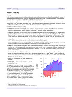
1 Introduction to Fluid PowerOnline NotesHydraulic CylindersPurpose of CylindersHere s the circuit diagram of lab #1 on the Hydraulic stand. From an energy standpoint, the purpose of the pump is to add energy to the Hydraulic fluid; the purpose of the cylinder is to extract energy from the Hydraulic fluid, to do useful lecture is about different kinds of Cylinders , how they work, and how we can use simple equations to figure out pressure, force, power, and velocity. In a manufacturing environment, these things matter. If you are installing a cylinder to move boxes of toothpicks on a high-speed packaging line, you would look for a cylinder that handles light loads at high speeds. If you are installing a cylinder in a garage to lift schoolbuses, you would look for a cylinder with a high load capacity that moves relatively slowly. If you are designing a Hydraulic sheet metal stamping press, you want a high load cylinder that moves of CylindersSingle-Acting CylinderThe simplest type of cylinder has one port.
2 Fluid flowing into the cap end of the cylinder pushes the piston and rod. The cylinder retracts under the force of a spring, the force of gravity (acting on a vertical the weight of a car on a vehicle lift), or by pumping the fluid squiggly line in the cylinder represents a compression spring in a spring-returned single-acting simplest type of single-acting cylinder is the ram, where the rodand piston are the same diameter (or nearly the same)..indeed, often they are a single part. The ram extends as fluid flows into the cylinder . Typically, we use the load (often under gravity) to make the ram can also use tension springs for retraction. Rams are used for elevators, jacks, and vehicle single-acting Hydraulic cylinder has a series of nested tubular shells called sleeves. You can have 4 to 5 sleeves in a typical telescoping cylinder . The load capacity will be based on the smallestdiameter sleeve in the assembly.
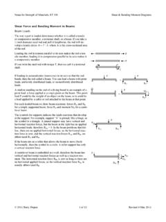
3 The advantage of this cylinder is its small size when maximum load that you can lift with a telescoping cylinder is the fluid pressure times the area of the smallest to Fluid PowerOnline NotesDouble-Acting CylinderMost Hydraulic Cylinders are double-acting Cylinders . They are also called differential Cylinders because the area that the fluid pushes onis different on each side of the piston therefore the extension forceis greater than the retraction force. On the left side, it s the cross-sectional area of the piston. On the right side, it s the cross-sectionalarea of the piston minus the cross-sectional area of the you let the rod extend out both ends of the cylinder , then you havea double-rod cylinder . They are also called nondifferential cylindersbecause the area that the fluid pushes on is the same on each side of the piston: the cross-sectional area of the piston minus the cross-sectional area of the rod.
4 Now the extension and retraction forces are CylinderWe can increase the force output from a cylinder by splitting it in two, and installing a second piston. Now the pressure pushed against a greater area, so the output is bigger. Typically, a tandem cylinder is built out of two shorter , Force, Velocity, & PowerForceConsider a double-acting Hydraulic cylinder , plumbed so that one side of the piston is pressurized, while the other side drainsto tank. Force generated by the cylinder is equal to the pressuretimes the area it acts on:F=pA. On the cap side, the area is the piston area, therefore Fext=pApiston. On the rod side, the area is the piston area minus the rod area, thereforeFret=p(Apiston Arod). Since the area for extension is larger, force during extension is larger than force during general, velocity v=QA, therefore vext=QApiston and vret=QApiston Arod. Retraction is faster than extension because the denominator in the retraction equation is use upper-case P for power, defined as the rate of doing work.
5 Since work is force times the distance it act through, we can write P=FSt where S is distance and t is time. Since v=St, P= a Hydraulic system, F=pA and v=QA, so P=Fv=pAQA= US Customary units for power are lb. , which you can convert to horsepower because hp= SI unit for power is the watt, where W=N sideRod sideA=ApistonA=Apiston ArodIntroduction to Fluid PowerOnline NotesPressure/Force/Velocity/Power Example #1A Hydraulic pump delivers of oil to a double-acting cylinder having a 6 cm piston diameter and a 2 cm rod diameter. The cylinder supports a load of 5000N in both directions; it shifts a heavy weight horizontally across a floor. Calculate pressure, velocity, and power for extension and for Fext=pApiston as pext=FextApiston=4 Fext dpiston2=4 5000N (6cm)2 kPa m2103N (100cm)2m2=1770kPavext=4Q dpiston2=4 (6cm)2 (100cm)2m2= kW s103N m= or Pext=pQext=1770kPa kNkPa m2 kW skN m= retraction, pret=FextApiston Arod=4 Fext [dpiston2 drod2]=4 5000N [(6cm)2 (2cm)2] kPa m2103N (100cm)2m2=1990kPavret=4Q [dpiston2 drod2]=4 [(6cm)2 (2cm)2] (100cm)2m2= kW s103N m= summary, we need more pressure to retract because the fluid acts on a smaller area.
6 We get a higher velocity on retraction because the fluid fills a smaller volume. We consume more power on retraction because power is force times Example #2 Consider a 1000 lb. weight pushed by a cylinder across a floor at a constant velocity. The friction coefficient = How much force is required?The first step is to draw a Free-Body Diagram of the block, showing all forces acting on the block. These forces include the weight W of the block due to the acceleration of gravity, the normal force N acting perpendicular to the surface that the block is sitting on, cylinder force Fcyl,and frictional force Ffr= solve the problem, use the principle of Sum of the Forces from Statics and Physics I classes. The sum of forces acting in one direction must equal zero if the body is still or is moving at a constant the vertical direction, the only two forces are W and N, acting in opposite directions, therefore N=W= the horizontal direction, the only two forces are Fcyl and Ffr, acting in opposite directions, therefore Fcyl=Ffr= N= to Fluid PowerOnline NotesPressure/Force/Velocity/Power Example #3 Consider a 1000 lb.
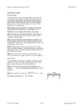
7 Weight elevated into the air by a cylinder at a constant velocity. How much force is required?Again we draw a Free-Body Diagram. Now there are only two forces acting on the block: W and Fcyl. We'll define axes x' and y', parallel and perpendicular to the direction of movement, to make the math the weight into two components acting in the x' and y' directions, so there are two forces acting along the line of direction: Fcyl and Wsin . cylinder force Fcyl=Wsin = = Example #4 Consider a 1000 lb. weight pushed up a 35 slope by a cylinder at a constant velocity. How much force is required?The Free-Body Diagram has four forces acting on the block. Again we break the weight into two components acting in the x' and y' , solve for the forces in the y' direction: N=Wcos .Next, solve for the forces in the x' direction. There are three forces: cylinder force, friction force, and the component of the weight that acts along the +Wsin = N+Wsin = Wcos +Wsin = (1000lb.)
8 Cos35 +(1000lb.)sin35 =164lb.+ accounts for 22% of the cylinder load; weight accounts for 78%. If you want to reduce the cylinder force, either lubricate the slope or install rollers on the = 35 W FcylWWcos Wsin x'y' = 35 WFcyl FcylWWcos Wsin x'y'NFfrIntroduction to Fluid PowerOnline NotesCylinder & Circuit Design IssuesEnd-of-Stroke ConditionsHere s another issue that comes up with Cylinders , whether they re Hydraulic or pneumatic. Let s say we re retracting a piston at a constant velocity, v= At the end of the stroke, v= Acceleration is defined as the change in velocity per unit of s how fast the velocity changes. In theory, the acceleration at the end of the stroke is infinite. In practice, it s finite, but very get impact. Over time,the hardware will break down. Keep in mind Newton s First Law:F=ma. If a is infinite (or extremely high), then F is infinite (or extremely high), no matter what the way to prevent Cylinders from shaking themselves apart is to install a cushion at the end of the cylinder .
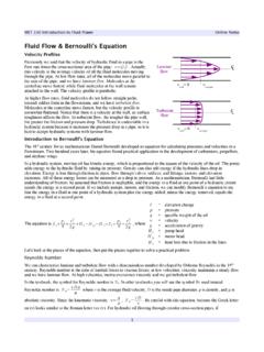
9 In a pneumatic cylinder , the cushion can be a piece of soft material. Another solution is to design the piston with an extra smaller diameter piston on the end, which fits into a cavity in the end of the cylinder . In the cartoon, the piston is moving pretty fast at the top, at a constant velocity. Next, the piston slows down, because all the flow has to go through a small hole. Motion of the piston is cushioned. Finally, the piston CircuitOne way to change the velocity of a cylinder is to change the plumbing. Consider the Hydraulic circuit from Lab #1: we have pump flow QP going from the pump, through the directional control valve (DCV), and to the cap side of the cylinder . We'll define the area of the piston as A1 and the area of the piston minus the area of the rod as A2. The velocity of the piston on extension is vext=QPA1, the pump flow rate divided by area A1. The force exerted by the piston on extension is Fext=pA1.
10 The velocityof the piston on retraction is vret=QPA2 and the force exerted by the piston on retraction isFret= let s change the plumbing, so the fluid coming out of the rod end of the cylinder joins the fluid coming from the flow from the rod end is called regenerative flow, or QR. The total flow to the cap end of the cylinder is QT=QP+ = 5 = 0 to Fluid PowerOnline NotesIn general, we can say that Q=Av, so total flow rate QT=A1vext and the regenerative flow rate QR=A2vext. Rewrite these equations to solve for the pump flow rate:QP=A1vext A2vext=(A1 A2)vext. Since A1 A2=ARod, we can writeQP=Arodvext, or vext=QPArod. We have a simple equation for extension velocity as a function of pump flow rate and rod area. Thecylinder diameter doesn t s just the rod diameter and pump flow rate that determine extension velocity. If you use a smaller rod diameter, you can increase the extension a free-body diagram of the piston during extension.