Transcription of Hydraulic Dock Leveler - wbmcguire.com
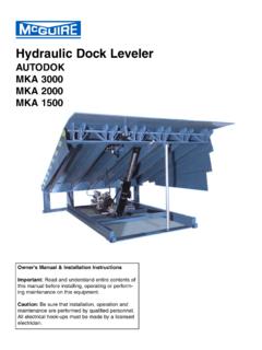
1 Hydraulic Dock Leveler AUTODOKMKA 3000 MKA 2000 MKA 1500 Owner's Manual & Installation InstructionsImportant:Read and understand entire contents ofthis manual before installing, operating or perform-ing maintenance on this :Be sure that installation, operation andmaintenance are performed by qualified electrical hook-ups must be made by a OF CONTENTSI ntroduction ..Overview of Potential Hazards ..Definition & Function-, Safety Practices ..Installation Instructions ..Pit Detail & Dimensions ..Shim Location Diagram ..Electrical Schematics ..Dock Bumper Mounting ..Operation Instructions ..Setting the Inspection Leg ..Maintenance & Service ..Trouble Shooting Procedures ..Control Valves & Motor Pump Adjustments ..Switch Arrangements .. Hydraulic System View & Parts List.
2 Control Panel View & Parts List ..Warranty ..INTRODUCTIONC ongratulations! You have just purchased one of the industry's finest hydraulically operated dock lev-elers from the mcguire Company Inc. of Hudson, NY When properly installed, operated andserviced, this Leveler can offer substantial efficiency and productivity. This mcguire Hydraulic dockleveler is the result of many skilled workers and its design, manufacture, and full Hydraulic operationare regarded with pride by the mcguire Company, Hydraulic dock Leveler by mcguire is designed to improve safety and efficiency for personnelinvolved in shipping and receiving goods at the loading dock area. Improved safety conditions areachieved by use of the control panel to operate the dock Leveler . This reduces the risk of injury bykeeping personnel off of the Leveler and eliminates the unhealthy practice of manually positioning theleveler.
3 Efficiency is the result of quicker operation, and a more reliable Hydraulic operating system requires minimal maintenance and provides you with years of dependable safety considerations should be observed by all those who install, operate and service this equip-ment. Even well-built products can be installed, operated and serviced in a less than safe this manual completely through to understand all installation, operation and maintenanceinstructions and functions before attempting to install, operate or service this Hydraulic dock special attention to all warnings and/or caution CoverWARNING!SAFETY INSTRUCTIONSIn the following sections the word:Danger means that serious injury or death willoccur from failure to follow that serious injury or death canoccur from failure to follow that minor injury or property damage canoccur from failure to follow means that special attention should be given to the Read manual carefully before installing, operating, or servicing dock Be sure truck wheels are chocked or truck is held in place by a restraining device before loading or Make sure Leveler is returned to its level, stored position after truck pulls away from Do not attempt to manually lift the dock Leveler platform or lip.
4 Do Not operate Leveler with equipment, material or people on the platform, lip or in front of the Keep pedestrians and forklifts away from open door area when not loading or unloading If dock Leveler appears to be broken or is not working properly, contact your authorized mcguire Ramp can cause serious injury or Clearwhen ramp is in Notenter pit area until ramp has been braced open andpower is turned off and locked Truckcan cause serious injury or Clearwhen truck is in Not stand between truck and ramp when truck is enteringor Shockcan cause serious injury or Power Offbefore touching wires or working in no power disconnect is provided, station a second person bythe control panel to insure no unauthorized LevelerMoving TruckMoving ShockOVERVIEW OF POTENTIAL AND FUNCTIONThe mcguire Hydraulic dock Leveler is designed for both structural integrity in operation and safetyfeatures for the protection of dock personnel.
5 Its function is to provide a safe and durable bridgebetween the building and the trailer. This bridge allows the safe transportation of material handlingdevices ( fork truck, pallet jack, hand truck) and workers for the purpose of loading and unloadingthe mcguire Hydraulic levelers are equipped with a velocity fuse "Fail-Safe" system which automati-cally halts all motion of the platform, within 1 " to 3", if a truck prematurely departs with a load on theplatform. Other safety features include full-range toe guards that are safety marked, a built-in serviceleg support and an automatic night lock feature to aid in the prevention of possible break-in attemptsthrough the dock Leveler is push button operated from a wall mount control panel and is fully electro-hydraulicoperated.
6 Models can be equipped with an Emergency Stop button which halts all movement of theleveler at any point during the cycle. A selector switch on the control panel allows automatic posi-tiong for below dock end load unit is powered by a 1 horsepower single or polyphase electric motor with manifold block and areservoir that is directly coupled to the motor via the manifold block. The main lift cylinder raises andlowers the platform. The lip cylinder extends, supports and retracts the lip. Flexible hosing connectsboth cylinders to the power leads from motor/pump and integral control switches are factory wired, ready to hook up toleads in the junction box at the rear of the pit. The control panel is wired to work in conjunction withthe motor/pump. Connections between terminals in the control panel and the pit junction box are notfurnished by mcguire .
7 This must be done prior to installing this Hydraulic Leveler . Connectionsbetween terminals in the control panel and the main power line are also not furnished by PRACTICES1. Do not operate this equipment while under the influence of drugs or Do not stand in the driveway between the Leveler and a moving Be sure that the trailer wheels are chocked or restraint device is Do not use the Leveler if appears to be broken or operating Do not operate the Leveler with equipment, material or people on the Be certain that nothing is on the Leveler while a truck pulls away from the Keep all limbs clear of the Leveler while it is in Do not attempt to manually lift the Leveler Always make sure the Leveler has been returned to the dock level (stored) Never work under the dock Leveler without proper placement of the service When servicing Leveler , disconnect power and tag control panel "Out of Service.
8 " Place a barrier on grade level in front of the Leveler to prevent any truck from backing to the the mcguire Technical Support Team at 1-800-624-8473 if you have anyquestions or do not understand any material presented in this INSTRUCTIONS CAUTION: Installation must be performed by qualified personnel : Always support the Leveler platform with suitable work under the Leveler without properly supporting the the Leveler for any possible damage that may have occurred during transportation. DO NOT INSTALL A DAMAGED that the control panel and bumpers are present. Report any damageimmediately to your the pit for proper construction. Clean out any debris. Check the pitwalls to make sure they are square and the pit dimensions to make sure they match the Leveler NOT INSTALL THE Leveler IF THE PIT IS NOT FORMED the control panel and mount it to the wall where the electrical leads will meet it.
9 A licensed electrician can now connect the control panel to the main power lead in and pull the proper leads through conduit and into the junction box at the rear of the pit. Refer to the proper wiring diagrams (pages 8-11 ) for proper Factory recommendation is for motor leads to extend from junction box for temporary power of Leveler and the Leveler with a fork truck using the built-in fork slots in the front base the Leveler so that the rear frame is approximately 36" from the rear of the licensed electrician can now connect the temporary extended motor leads from the junction box to leads in the rubber covered cable from the Leveler motor. Refer to wiring diagram, the fork truck out approximately 24" but keep forks in the slots. Check for proper wiring by operating the Leveler .
10 (See Operation Instructions, pages 13-14).NOTE- On three phase current, check for proper motor rotation per wiring Leveler does not raise when pump is energized, the rotation is wrong. Correct by reversing two power leads to proper operation is achieved, move the Leveler to within 12" from the rear of the pit. The licensed electrician can now make permanent wiring hook-ups and close the junction : DO NOT enter pitarea until Leveler has been bracedopen with jack INSTRUCTIONS (continued) the Leveler so that there is 1 " of clearance on both sides. Push the Leveler all the way into the pit, so that the rear frame of the Leveler is flush and tight against the rearcurb angle of the pit. Tack weld the Leveler to the rear curb angle of the pit at both fork truck can be removed from the area.