Transcription of Hydraulic Flanges and Components - mdmetric.com
1 Hydraulic Flanges and ComponentsThe Fitting AuthorityM2 Parker Hannifin CorporationTube Fittings DivisionColumbus, Catalog Hydraulic Flanges and ComponentsB3 HQCode 61, 62 / Flareless M11 Flange ClampsStraight Flange Adapters / FlangesFHS3 Code 61 Flange Clamps Metric M8 FHS6 Code 62 Flange Clamps Metric M9 BUHQ1 Code 61 / Flareless M10 BFGDIN Flange / Metric Flareless M13 GFSCode 61, 62 / Metric Flareless M12 FCCF lange Clamp Captive M7 FCSF lange Clamps Split M7 PFlange Head Plug M13G5 HQFlange Head / SAE-ORB M14WB3/5/7HQ2 Code 62 / Weld Butt Pipe M15WB1/3/5HQ1 Code 61 / Weld Butt Pipe M15G5 QCode 61, 62 / SAE-ORB M16 GQCode 61, 62 / NPT M16G4 QCode 61, 62 / BSPP M1790 Flange AdaptersXHQCode 61, 62 / 37 Flare M10 LOHQCode 61, 62 / ORFS M10 GHQF lange Head / NPT M14 LOEQCode 61, 62 / ORFS M29 XEQCode 61, 62 / 37 Flare M29 WFSCode 61, 62 / Metric Flareless M31W7 EQCode 61, 62 / Weld Socket Pipe M30 BUEQ1 Code 61 / Flareless M29W5 QCode 61, 62 / Socket Pipe M18W7 QCode 61, 62 / Ext Socket Pipe M20W4 QCode 61, 62 / Socket Tube M19WB1/3/5Q1 Code 61 / Weld Butt Pipe M22W6 QCode 61, 62 / Ext Socket Tube M21WB3/5/7Q2 Code 62 / Weld Butt Pipe M23 ASCode 61, 62 / Weld Butt Tube Metric M24 WBTCode 61 / Weld Tank Adapter M24 WSDCode 61, 62 / Weld Saddle M25 GQSS quare Flange / NPT M25W5 SQSS quare Flange / Weld Socket Pipe M26 PQCode 61, 62 / Blank M26 SPGG5 Flange Spacer w/Gage Ports M27 CPFlange Connector Plate M27 BUVQ1 Code 61 / Flareless M28 LOVQCode 61, 62 / ORFS M28 XVQCode 61.
2 62 / 37 Flare M2845 Flange AdaptersF5 OHQCode 61, 62 / SAE-ORB M11W7 HQFlange Head / Pipe Socket M14M3 Parker Hannifin CorporationTube Fittings DivisionColumbus, Catalog Hydraulic Flanges and ComponentsStainless Steel FlangesGQCode 61, 62 / NPT M36G5 QCode 61, 62 / SAE-ORB M36 PQCode 61, 62 / Blank M38 BFWDIN Flange / Metric Flareless M32 GEQCode 61, 62 / NPT M34G5 EQCode 61, 62 / SAE-ORB M33W6 EQCode 61, 62 / Weld Socket Tube M35 QPQPJQCode 61, 62 Junction Tee M33 TeeW5 QCode 61, 62 / Weld Socket Pipe M37 Code 61/62 Flange Seal O9 ORFS O-Ring O3 SAE 4-Bolt Flange O-Ring O9O-Rings and SealsO-Rings and Seals (Shown in Section O)Parflange 1050 S24 Flanging ToolsEquipment (Shown in Section S)90 ElbowsM4 Parker Hannifin CorporationTube Fittings DivisionColumbus, Catalog Hydraulic Flanges and ComponentsIntroductionThe 4-bolt flange connections conforming to SAE J518 and ISO 6162-1 and -2 are proven, leak-free connections, especially suited for larger sizes, higher pressures and assembly in tight quarters.
3 Threaded port connections such as SAE straight thread O-ring and ISO 6149 are reasonably easy to assemble and provide 6000 psi and higher pressure capability up to size 12 (M27). Beyond this size the pressure rating starts to decrease and assembly torques increase rapidly. The 4-bolt flange port connections provide ability to connect larger sizes and achieve higher-pressure capability at reasonable assembly torques. Be-cause of the lower assembly torques compared to an equivalent size threaded port, these connections are well suited for tight quarters where wrench clearances are limited. Parker 4-bolt flange products described in this part of the catalog provide various means of connecting tubes, hoses, pipes and threaded fittings to 4-bolt flange ports. The discussion below provides an overview of some of the available flange and ConstructionParker 4-bolt flange products are designed to provide different methods of connecting a tube, hose, pipe or another fitting to the SAE standard 4-bolt flange Fittings All Parker flange fittings, except for those with square mounting hole patterns (nomenclature code QS), are designed to conform to O-ring groove, bolt holes and bolt pattern dimensions of either Code 61 or Code 62 of SAE J518 and ISO 6162-1 (Code 61) or -2 (Code 62).
4 The flange adapters (Code Q1 and Q2), and flange block fittings (Codes Q1B, Q2B and QSB) have O-ring grooves conforming to dimensions in SAE J518. The flange block fittings (Codes Q1B and Q2B) have through holes for the mounting bolts, again conforming to SAE J518. There is no industry standard for the bolt pattern of the square pattern block Flanges with codes QSP and flange pad fittings (Codes Q1P, Q2P, and QSP) have a flat face (no O-ring groove) and the mounting holes are tapped. Where these fittings are used, the seal is in the mating part (flange adapter, flange hose fitting, flange block fitting, etc.) as shown in Fig. M2 Assembly / Removal SAE J518 Connection Parflange SleeveCode 61/62 ClampSeal PlateFig. M1 Flange Pad FittingFlange Pad FittingFlanged Hose FittingO-ring Seal in Hose FittingFlange Clamps Clamps are used for providing the holding power to the 4-bolt flange connection.
5 They are offered in split and captive (one-piece) versions. The captive version is also of-fered with either drilled or tapped bolt holes. The captive flange clamp with tapped holes is used while connecting a tube to another tube or a flange clamps are forged for higher strength and durability. They meet all requirements of SAE J518. The split clamps make it easy to assemble the connection in close quarters. They also make removal of the flange head component, such as a hose assembly, easy by loosening all four bolts and removing one clamp half, as shown in Fig. Block Tees These are solid block union fittings to connect two tube/hose assemblies using 4-bolt flange connec-tion, at a junction, to SAE 4-bolt flange port, or three tube/hose assemblies to each Plate Connector plate is used as a middle plate to connect two flange heads with O-ring grooves, such as two hose assemblies with flange connection ends.
6 The flat surface of the plate provides sealing surface on each side for the O-ring housed in the hose Plate Spacer plate provides access to the system fluid via the gage port on the side. The plate is between the flange connection to provide this Plugs provide a means to block off the 4-bolt flange port with and without clamps, and to plug the end of a pipe (via welding).Tank Weld Adapter Tank weld adapters provide a means of flange connection to a fabricated reservoir or other than the O-ring groove, bolt holes, bolt pat-tern, and the flange foot print (for codes Q1B and Q2B only) are not governed by any industry standard. However, Parker product design follows common industry practice and sound M1 Standard Material Specifications for Hydraulic Flanges and ComponentsNote: Split flange clamps are zinc clear (or Cr6 free) chromate.
7 All other steel Flanges are oil FlangesSteelStainless SteelASTMTypeASTMType4-Bolt FlangesA108C1020A240316 LFlange ClampsA108C1045A351 / A743 Nitronic 50 HHCS BoltsSAE Grade 8 SHCS Bolts A240316M5 Parker Hannifin CorporationTube Fittings DivisionColumbus, Catalog Hydraulic Flanges and ComponentsDimensions and pressures for reference only, subject to M3 Four-Bolt Flange Connection (SAE J518) Code 61/62 ClampTube or Hose EndFlange HeadO-RingClamping BoltHow Flange Connections WorkThe four-bolt flange connection (SAE J518) is a proven leak-free connection, especially suited for larger sizes. As a result, it has achieved worldwide connection s success is in its simplicity. It is a static face seal using a high durometer O-ring for the seal and clamps and bolts for holding power as shown in Fig.
8 M3. Alternatively, a bonded seal plate is between the port face and the flat face of a mechanically formed (flanged with Parflange process) tube as shown in Fig. M4 to achieve the same (O-ring) seal is compressed between the bottom of the groove in the flange head and the flat surface of the port or flange pad, providing a reliable soft seal. The alternate seal plate has a high durometer bonded rubber seal on the inside edge, which compresses between the two flat surfaces, providing a soft seal with the same reliability. A metal-to-metal contact at the outer face of the flange with the port face keeps the seal from extruding under pressure. This metal-to-metal contact is maintained by the clamping force provided by tightening the bolts via the simple design provides several advantages over threaded port connections, such as NPTF, SAE, BSPP, ISO 6149, etc.
9 , in larger sizes: Ability to connect up to 5 inch tube (Code 61 only) Much lower tightening torque required from the four bolts compared to that required for equivalent size threaded port Less tightening torque means smaller wrenches and wrench swing clearances providing ease of as-sembly in tight quarters Up to 6000 psi capability through 2 size (Code 62 only) Single seal point between tube/pipe/hose assembly and the port Ease of disassembly through use of split clampsThe connection has one disadvantage it requires a larger area (foot print) on the component than an equivalent threaded and InstallationPlease refer to Section T for the assembly and installation instruc-tions for Hydraulic Flanges and Components M4 Formed Tube with ISO 6162 (SAE J518) Connection Parflange SleeveCode 61/62 ClampSeal PlateTubeFeatureAdvantageBenefitConform to SAE J518 and ISO 6162 Controls dimensions and tolerances of code 61 and 62 port connectionsInsures interchangeability and consistencyForged ConstructionReliable, long life performanceNo downtime, reduced costsCompact envelope size, no sharp edgesReduced weightOver 60 ConfigurationsFlexibility in plumbing, match system needsBest solution and best valueParflange TechnologyDesigned to be used with Code 61/62 fittingsEliminates messy and time consuming brazing processMounting HardwareGrade 8 bolts standardPerforms in rigorous applications for the life of the flangeFlange KitsFlange with hardware for mounting (o-ring, bolts and lockwashers)
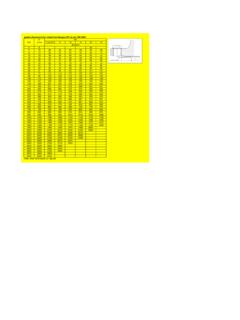
10 Reduces order and assembly errorM6 Parker Hannifin CorporationTube Fittings DivisionColumbus, Catalog Hydraulic Flanges and ComponentsDimensions and pressures for reference only, subject to HeightSIZEC(inch)D Max(inch)E(inch)CODE 61 and Code 62 Port EndsM7 Parker Hannifin CorporationTube Fittings DivisionColumbus, Catalog Hydraulic Flanges and ComponentsDimensions and pressures for reference only, subject to FITTING PART #FLANGE SIZE (in.)A (in.)B (in.)D (in.)E (in.)H (in.)K DRILL DIA. (in.)L (in.)M (in.)T TAP UN-2BX (in.)Y (in.)MOUNTING HARDWARESTANDARD Dynamic Pressure (x 1,000 PSI)DRILLED HOLESTAPPED HOLESHHCSSXSSCODE 61 FLANGE CLAMP, 5/16-18 5/16-18 x 3/8-16 3/8-16 x 3/8-16 3/8-16 x 7/16-14 7/16-14 x 1/2-13 1/2-13 x 1/2-13 1/2-13 x 1/2-13 1/2-13 x 5/8-11 5/8-11 x 5/8-11 5/8-11 x 5/8-11 5/8-11 x 62 FLANGE CLAMP, 3/8-16 3/8-16 x 7/16-14 7/16-14 x 1/2-13 1/2-13 x 5/8-11 5/8-11 x 3/4-10 3/4-10 x 61/62 Flange Clamp, CaptiveFCSCode 61/62 Flange Clamps, SplitTo order a flange clamp split kit.