Transcription of Hydraulic Motor/Pump Series F11/F12
1 Catalog 9129 8249-06 February 1999, USHydraulicMotor/PumpSeries F11/F12 Fixed Displacement2 Hydraulic motor /PumpSeries F11/F12 ContentPageGeneral information3F11 cross section3F12 cross sections4 Specifications5 Ordering codes: - F116- F127 Bearing life8 Efficiency9 Noise level9 Selfpriming speed andrequired inlet pressure10 Installation dimensions: - F11-5 and -10 CETOP11- F11-19 CETOP12- F11-19 SAE13- F12 ISO14-F12 Cartridge16- F12 SAE 4 bolt flange18- F12 SAE 2 bolt flange20- F11-150 CETOP22- F11-150 SAE23- F11-250 SAE24F11 saw motors25F11 fan motors25F12 integrated flushing valve26F12 accessory valve blocks.
2 - Type FV 13 (F12-110)26- Type BT brake valve27- Type SR pressure relief/make-up valve27- Type SV pressure relief valve28F12 speed sensor28F12 main port flanges29 Installation information30 Conversionfactors1 lb1 lbf1 lbf ft1 psi1 US gallon1 cu in1 in9/5 C + 321 FParker Hannifin reserves the right to modify productswithout prior though the brochure is revised and updatedcontinuously, there is always a possibility of more detailed information about the products,please contact Parker Hannifin (VOAC Hydraulics Div.).3 Hydraulic motor /PumpSeries F11/F12 General informationF11 and F12 are bent axis, fixed displacementheavy-duty Motor/Pump Series .
3 They can be usedin numerous applications in both open and closedloop circuits. Series F11 is available in the following framesizes and versions:- F11-5, -10, 19 and -150 with CETOP mountingflange and shaft end- F11-19, -150 and -250 with SAE flange andshaft Series F12 conforms to current ISO and SAEmounting flange and shaft end very compact cartridge version is sizes: F12-30, -40, -60, -80 and -110. Thanks to the unique spherical piston design, F11/F12 motors can be used at unusually highshaft speeds. Operating pressures to 7000 psiprovides for the high output power capability. The 40 angle between shaft and cylinder barrelallows for a very compact, lightweight Motor/Pump .
4 The laminated piston ring offers importantadvantages such as low internal leakage andthermal shock resistance. The pump version has highly engineered valveplates for increased selfpriming speed and lownoise, available with left and right hand rotation. The F11/ F12 motors produce very high torqueat start-up as well as at low speeds. Our unique timing gear design synchronizesshaft and cylinder barrel, making the F11/F12very tolerant to high 'G' forces and torsionalvibrations. Heavy duty roller bearings permit substantialexternal axial and radial shaft loads. The F11's and F12's have a simple and straight-forward design with very few moving parts,making them very reliable motors/ pumps .
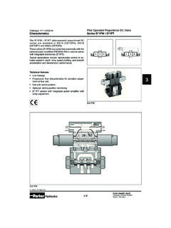
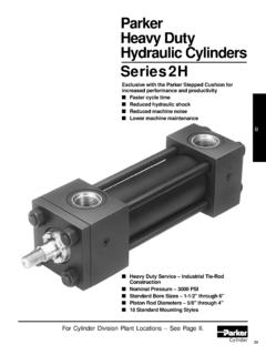
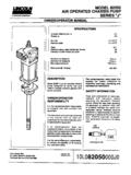
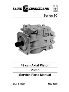
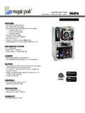
5 The unique piston locking, timing gear andbearing set-up as well as the limited number ofparts add up to a very robust design with longservice life and, above all, proven 67891. Barrel housing2. Valve plate3. Cylinder barrel4. Guide spacerwith O-rings5. Timing gear6. Roller bearing7. Bearing housing8. Shaft seal9. Output/input shaft10. Piston with laminatedpiston ringF11 cross section4 Hydraulic motor /PumpSeries F11/F12F12 cross sections1. Barrel housing2. Valve plate3. Cylinder barrel4. Piston with piston ring123456789123104567891211F12-30, -40, -60 and -80(F12-60 shown)5. Timing gear6. Tapered roller bearing7.
6 Bearing housing8. Shaft seal9. Output/input shaft10. Port E (F12-110)11. Cylindrical roller bearing12. Needle bearingsF12-110 Legend:5 Hydraulic motor /PumpSeries F11/F12 Frame sizeF11-5-10-19F12-30 -40-60-80-110 F11-150 -250 Displacement [cm3/rev] [cu in/rev] operating speed [rpm]max intermittent12 000 10 000 7 5007 100 6 400 5 600 5 200 4 7003 0002 700max continuous8 500 6 800 5 4005600 5000 4300 4000 36002 6002 400min continuous2002005050200200 Max pump selfpriming speedL or R function; max [rpm]4 600 4 200 3 5002850 2650 2350 2350 22001 7001 500 Torque (theor.)
7 At 100 bar [Nm] 1000 psi [lbf-ft] input flowmax intermittent [l/min]5898143213256335418517450650[gpm] continuous [l/min]4167103168200257322396390580[gpm] power ( motor ) max intermittent [kW]182845110130175220270200300[hp]24386 0150175235295360268402max continuous [kW]1320327085110153165145190[hp] pressuremax intermittent [bar]420420480480420420[psi]6 0006 0007 0007 0006 0006 000max continuous [bar]350350420420350350[psi]5 0005 000600060005 0005 000 Max case pressure shaft seal type H, 1500 rpm [bar] [psi]290290275200175175145140140140 Main circuit temp., max [ C]757580807575[ F]165165175175165165 min [ C]-35-35-40-40-35-35[ F]-31-31-40-40-31-31 Fluid viscosity, max.
8 [mm2/s]1 0001 000[SUS]5 0005 000min. [mm2/s]1010881010[SUS]606058586060 Fluid contamination level18/1318/13(ISO code 4406)Mass moment of inertia(x10-3) [kg m2] [ft lb s2] [kg] [lb] motor /PumpSeries F11/F121. Frame size51019 150 2505. Shaft sealNNitrile, low pressure--xxxHNitrile, high pressure--(x ) (x )(x)EViton (low pressure,high temperature)--(x ) (x )(x)6. ShaftTSAE key--xx-SSAE spline--(x ) (x )-KMetric key----xFSAE spline----(x)7. Serial number (assigned for special versions)1. Frame size51019 150 2502. FunctionMMotor--xx-HMotor, high pressure--xx-QMotor, silent--(x) (x )x3)JMotor, clockwise rot'n1)--(x)(x)-GMotor, counter )--(x)(x)-RPump clockwise rot'n--xxxLPump counter Main portsUSAE, UN threads--x--BBSP threads--(x)--FSAE 6000 psi flange4)-- - x x4.
9 Mounting flangeSSAE flange--xxx1. Frame size51019 1505. Shaft sealNNitrile, low pressurexxxxHNitrile, high pressure(x ) (x ) (x ) (x)EViton (low pressure,high temperature)(x ) (x ) (x ) (x)6. ShaftKMetric keyxxxxDSpline, DIN 5480(x ) (x ) (x ) (x)7. Serial number (assigned for special versions)1. Frame size51019 1502. FunctionMMotorxxxxHMotor, high pressurexxxxQMotor, silent(x) (x ) (x) (x)JMotor, clockwise rot'n1)(x) (x) (x) (x)GMotor, counter )(x) (x) (x) (x)RPump clockwise rot'nxxxxLPump counter motor -xx-3. Main portsBBSP threadsxxx-RWith anti-cavitationvalve; clockw.
10 Rot n2)-x x -LWith anti-cavitationvalve; counter )-x x -USAE, UN threads(x) (x ) (x)-FSAE 6000 psi flange---x4. Mounting flangeCCETOP flangexxxxWSaw motor flange-xx-Ordering codes12 3 4 5 6 7 Example: F11 - 10 - M B - C N - K - 000F11-SAE12 34 5 6 7 Example: F11 - 19 - H U - S N - T - 000x: Available(x): Optional : Not available1) Internal drain3) Standard4) Metric threadF11-CETOPx : Available(x): Optional : Not available1) Internal drain2) BSP threads7 Hydraulic motor /PumpSeries F11/F121. Frame size30406080 1102. FunctionMMotorxxxxx3. Main portsFISO flangexxxxx4.