Transcription of Hydraulic-Training Axial Piston Units Basic Principles
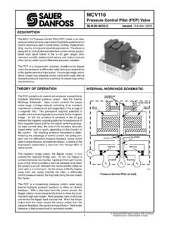
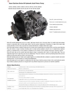
1 EngineeringRexrothmannesmannBrueninghaus HydromatikHydraulic-TrainingAxial Piston UnitsBasic PrinciplesRE 90600 Piston Units1 Basic of2- 3 Hydraulic Circuit2 Principles of of of Group Piston ,Bent-AxisRotary of Description of of Group Rotary of Selection of TypicalModels from theindividual Product Modelstoof Bent-Axis of Control DevicesPageAxial Piston UnitsTitle2 Axial Piston UnitsTitleIndexOpen CircuitThe Way to the complete Hydraulic System:(explanation of symbols, see page 3) Basic system with hydraulic pump and hydraulic motor (orcylinder). Single direction of input, output and directional control valve allows reversal of the direction ofrotation or of movement at the output speed is achieved by installation of a flowcontroller for variable flow. The pressure relief valve (DBV)protects the system from , the fixed pump and flow controller have been replaced bya variable pump.
2 Further valve functions have been added, of the user. Filter, cooler and other accessoriesare also of Hydraulic CircuitOpen circuit normally means the case where the pumpsuction line leads below a fluid level whose surface isopen to atmospheric pressure. Maintenance of a pres-sure balance between the air in the hydaulic tank andthe air in the atmosphere guarantees good pump suctioncharacteristics. There must be no resistance in the inletline which might cause pressure to drop below theso-called suction head/suction Piston Units are self-priming; in certain specialcases, however, a low pressure is applied to the open circuit hydraulic fluid is fed to the user via direc-tional control valves and returned to the tank in thesame features of the open circuit are:nsuction lines - short length, large diameterndirectional control valves - flow-related sizesnfilter / cooler - flow-related sizesntank size - a multiple of the max.
3 Pump flow in litresnpump arrangement - adjacent to or below the tankndrive speeds - limited by the suction headnload maintained in return by valvesThe open circuit is standard in many industrial andmobile applications - from machine tools, throughBasic PrinciplesFor the hydraulic engineer, there are three Basic typesof circuit to consider:open circuitclosed circuitsemi-closed circuitIn the following we look at open and closed circuits insome details. The semi-closed circuit is a mixture of thesetwo types of circuit and is used in applications wherevolume compensation via prefill valves is necessary( when using a single rod cylinder).flowQ = constantoutput speedn = constantinput speedn = constantsuction linetank size (litres)lifting speedv = speedinput speedn = constantoutput speedn = constantlifting speedflowQ = constantinput speedn = constantoutput speedn = variablelifting speedv = variabledirectionof liftingflowQ = variableoperating positiondirectionof positionlifting speedv = variableflowQ = variableoutput speedn = variableinput speedn = constant3 Axial Piston CircuitA hydraulic system is described as closed when thehydraulic fluid is returned from the user direct to is a high pressure and a low pressure side,depending on the direction of load (take-off torque atthe user).
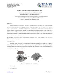
4 The high pressure side is protected by pressure reliefvalves which unload to the low pressure side. Thehydraulic fluid remains in the the continuous leakage from pump and motor(dependent on operating data) must be fluid is normally replenished by an auxiliary pumpflanged direct onto the main pump which delivers acontinuous, adequate supply of fluid (boost fluid) froma small tank via a check valve into the low pressureside of the closed circuit. Any surplus flow of the boostpump, which operates in open circuit, is returned via aboost-pressure relief valve to the tank. The boostingof the low pressure side enhances the features of the closed circuit for Axial pistonunits are:ndirectional control valves - small sizes for pilotoperationnfilter/cooler - small sizesntank size - small, dimensioned to suit boostpump flow and volume of systemnspeed - high limiting values through boostnarrangement/mounting - position-flexible/optionalndrive - completely reversible through centrepositionnIoad maintained - via the drive motornfeedback of braking powerExplanation of Symbols / Colour Code for Open and Closed CircuitsAn auxiliary pump for replenishment of leakage oil and control ofthe pump.
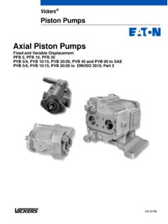
5 Boost check valve RV. Boost pressure relief valve filter, cooler and Principles Closed CircuitA Step-by-Step Guide(explanation of symbols, see below left) Basic system with variable pump and variable motor. Single pumpinput drive direction. Motor power take-off in both directions. Thepump can be swivelled smoothly over centre, the direction offlow is reversible. Pressure relief valves, one each for the high and low pressuresides, prevent the maximum permissible pressure from leakage from pump and motor is led back to a small tank andmust be replenished!Q = variablepumpmotoroil tankleakage oilboost checkvalvefor pump controlauxiliarypumpfiltercoolerred(high ) pressure lineblue(low, boost) pressure linebluesuction linegreenreturn line (tank, bypass pressure)greenleakage lineyellowhydraulic components (pump, motorcylinder, valves, accessories)orangecontrol element (solenoids, springs)boostcheckvalveboostpressurevalv e4 Axial Piston UnitsTitleIndexSchematic Diagram of a Bent-Axis Unitwith fixed or variable swivel angle 2 Principles of AxisExample: fixed displacement Unitwith tapered Piston rotary grouph= Piston strokeA= Piston areaDT= pitch diameter ofdrive shaft = swivel angle ( 25o)Vg= geom.
6 displacement [cm3/rev.]x= number of pistons ( 7)h=DT sin Vg= x A hVg= x A DT sin Principles of Function drive shafttapered pistoncylinderport plate for = constantkidney-shapedcontrol slotscontrol lens for = variablecenter position5 Axial Piston UnitsTitleIndexrotation of the drive shaft also causes the cylinder torotate without the need for a Cardan coupling. Thepistons execute a stroke within the cylinder boresdependent on the angle of inclination of the bent hydraulic medium is fed to the low pressure (inlet)side of the pump and pumped out by the pistons onthe high pressure (outlet) side into the Function:In motor operation, the process is reversed andpressure oil is fed to the inlet side of the unit. Thepistons perform a stroke which is converted via theflexible Piston mounting on the drive flange into a rotarymovement.
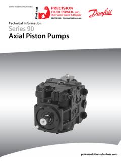
7 The cylinder rotates with the pistons,generating an output torque on the drive shaft. Oilexiting on the outlet side flows back into the Angle:The tilt/swivel angle of the fixed displacement unit isdetermined by the housing and is therefore fixed . On avariable unit, this angle is infinitely variable withinspecific limits. Changing the swivel angle changes thepiston stroke, thus allowing variable PrincipleDescriptionThe Axial Piston Units of bent-axis design with fixed orvariable displacement can operate as hydraulic pumpsor hydraulic = drive shaft2 = piston3 = Piston area4 = cylinder5 = pressure stroke6 = suction stroke7 = port plate8 = upper dead point OT9 = lower dead point UT10 = control slot, pressure side(for direction of rotation shown)11 = control slot, suction side(for direction of rotation shown) of FunctionExample: fixed displacement UnitThe bent-axis rotary group is a displacement unitwhose displacement pistons are arranged at an angleto the drive Function.
8 Through the flexible Piston / Piston rod arrangement, Principles of FunctionWhen used as a pump, the flow is proportional to theinput speed and the swivel angle. If the unit is used asa motor, the output speed is proportional to the flowthrough the unit. The input (pump) or output (motor)torque increases with the pressure drop between thehigh and low pressure sides. In pump operation,mechanical energy is converted into hydrostatic power,while in motor operation, inversely, hydrostatic poweris converted into mechanical energy. By adjusting theswivel angle of a variable pump or motor it is possibleto vary the displacement and thus the as a pump in open circuit:On rotation of the drive shaft, the cylinder is caused torotate by seven pistons flexibly mounted in a circulararrangement on the drive shaft. The cylinder slides onthe spherical port plate which has two kidney-shapedcontrol slots.
9 As the cylinder rotates, each of the sevenpistons moves from the upper dead point OT to thelower dead point UT and back, thereby executing astroke dependent on the swivel angle. The pistonmovement from the lower to the upper dead point inthe cylinder bore produces the suction stroke, wherebya quantity of oil relative to the Piston area and pistonstroke is sucked in through the control slot on thesuction Piston UnitsTitleIndexQ =(l/min)Drive speedn = (rpm)FlowQ = (l/min)On further rotation of the drive shaft, as the pistonsmove from the upper to the lower dead point, oil ispushed out through the other control slot (pressureside). The pistons are held against the drive shaft byhydraulic as a motor:The motor function is the reverse of the pump this case, hydraulic oil is fed via the connection platethrough a control slot to the cylinder bores.
10 3 or 4cylinder bores are located over the pressure sidecontrol slot, 4 or 3 over the return-line side, with onebore possibly being covered by part of the port platedirectly at the dead point. The force generated as aproduct of pressure and Piston area acts on the driveshaft to produce the output Function: (with control devices fitted)The swivel angle of the bent axis can be changed, forexample, mechanically via an adjusting spindle orhydraulically via an adjusting Piston . The hydraulicsection of the rotary group cylinder complete withcontrol lens (port plate) is swivelled out and, dependingon the type of circuit and function, is held in the zeroor starting position by either mechanical or hydraulicmeans. Increasing the swivel angle increasesdisplacement and torque; decreasing the angle givesa corresponding reduction in these values.