Transcription of Hydro 2000 - Grundfos márkaszerviz
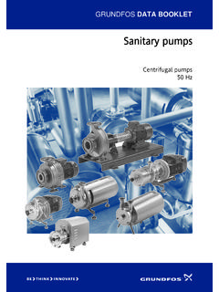
1 Grundfos DATA BOOKLETH ydro 2000 Grundfos Hydro 2000 booster sets with 2 to 6 CR(E) pumps50 Hz2 ContentsProduct dataPerformance range3 Hydro 20004 Control 2000 4 Functions 4 Application and need5 Water supply 5 Industry 5 Irrigation 5 Type key6 Construction 6 System configuration7 Hydraulic functionsOverview of functions8 Product rangeSystem overview10 SizingGeneral information 12 Consumption pattern 12 System selection13 Type of booster set14 System size15 Diaphragm tank16 Dry-running protection 16 Friction-loss compensation 16 Understanding the curve charts18 Example: How to select a system19 Performance curves, Hydro 2000 SCR 3 20CR 5 22CR 10 24CR 15 26CR 20 28CR 32 30CR 45 32CR 64 34CR 90 36 Technical data, Hydro 2000 S Electrical dataCR 3/ CR 5 38CR 10 40CR 15 42CR 20 45CR 32 48CR 45 50CR 64 52CR 90 54 Performance curves, Hydro 2000 F-ECR 3 56CR 5 58CR 10 60CR 15 62CR 20 64CR 32 66CR 45 68CR 64 70CR 90 72 Technical data, Hydro 2000 F-E Electrical dataCR 3 74CR 5 76CR 10 79CR 15 82CR 20 85CR 32 87CR 45 90CR 64 92CR 90 95 Technical dataDimensions and weights98 Construction 98 Operating conditions 98 Installation 98 Mechanical installation 98 Electrical connection 98 Further product documentationWinCAPS 99 WebCAPS1003 Product dataHydro 2000 Performance rangeTM02 7576 3803124681020406080100200400600800Q [m /h]
2 2030405060708090100150H[m] Hydro 200050 HzISO 9906 Annex ACR 45CR 32CR 20CR 15CR 10CR 90CR 64CR 3CR 54 Product dataHydro 2000 Hydro 2000 The Grundfos Hydro 2000 booster set consists of 2 to 6CR(E) pumps coupled in parallel and mounted on acommon base frame provided with all the necessaryfittings and a Grundfos Control 2000 sets with up to 8 pumps are available delivered, the Grundfos Hydro 2000 booster setis factory-tested and set according to the customer swishes, ready for 1 Hydro 2000 pressure boosting systemControl 2000A Grundfos Control 2000 control cabinet holds aPFU 2000 (Pump Functional Unit 2000 ).The Grundfos Control 2000 may also be supplied witha PMU 2000 (Pump Management Unit 2000 ).FunctionsControl 2000 offers the following functions: Performance control. Grundfos bus communication.
3 Stop function when operating at low flow (increases the efficiency when operating at low flow). Automatic cascade control of pumps. Automatic changeover between pumps in operation (ensures the same number of operating hours for all pumps). Manual operation (enables testing of individual pumps). Various setpoint influences: friction-loss compensation (pressure decreases with a decreasing flow) setpoint adjustment via external signals (temperature, time, level and flow). Various digital remote-control functions: start/stop of system reduced operation (limits the maximum number of pumps in operation) 2-point control of the setpoint (enables control of the setpoint by means of 2-point contact) 3-point control of the setpoint (enables control of the setpoint by means of 3-point contact) firefighting operation . Pump and system monitoring functions: minimum and maximum limits for the value measured pre-pressure measurement motor protection Grundfos bus communication.
4 Display, alarm and signal functions: 2 x 24 character LCD display indicator lights for operating and fault indication(green and red light-emitting diodes) potential-free changeover contacts for operating and fault signals. Clock program . Setting can be changed only when a PMU 2000 5391 1302TM00 2721 1302 PFU 2000 Simple operationTM00 7023 1302 PMU 2000 Advanced operationEnables regular optimisation of operating conditions and read-out of operating 2000 PFU 2000 PumpPressuretransmitterNon-returnvalveIs olatingvalvePressure gaugeReset5 Product dataHydro 2000 Application and needAbundant water is the key to progress and booster set should be planned the right way whetherused for water supply, industrial purposes or purpose is to optimise operating costs and achievea high degree of comfort. The starting point when planning a booster set is supply area has its own consumption Grundfos Hydro 2000 booster set can be used fora wide range of applications.
5 A number of typical exam-ples are shown supplyAccess to the right quantity of clean water at the righttime is the key to a healthy term water supply covers: waterworks, pressure boosting in distribution circuits blocks of flats, schools, hotels, hospitals, of the water consumption in a typical water-works have revealed large differences in the daily waterconsumption pattern. Consumption is characterised by: sudden variations between min. and max. consump-tion variation taking place over long periods constant 2 Typical consumption pattern in waterworksIndustryIn a number of processes, water plays a vital part. Theindustrial consumption pattern varies with the type ofindustry. Many manufacturing processes consist of acycle requiring an absolute constant pressure evenwhere large and very quick flow variations areconcerned.
6 Among others, industrial pressure boosting and liquidtransfer comprise: the food industry the textile industry the petrochemical industry the pharmaceutical general, consumption is characterised by: large variations from minimum load to peak load sudden variations constant 3 Typical industrial consumption patternIrrigationIn order to maintain recreational areas used for specificpurposes, it may be necessary to term irrigation covers: gardening parks sports grounds, typical irrigation system could be used in connectionwith a golf course. When the irrigation system isstarted, consumption depends on the number of sprin-klers typical irrigation system is characterised by: irrigation zones variable, but known consumption system divided into pressure 4 Typical consumption pattern in irrigation applicationTM00 9197 1303 QhTM00 9200 1303TM00 9198 1303 QhQh6 Product dataHydro 2000 Type keyConstructionFig.
7 5 Hydro 2000 booster setExampleHydro 2000 MEH/G/NS2CR 10-32 CRE 5-5 PMU3 x 400/230 V, 50 HzType rangeSubgroups:MS, MSH, MF, MFH, ME, MEH, MESM anifold material:: Stainless steel/C : Copper/G : Galvanised steelSuction manifold fitted:: With suction manifold/NS: Without suction manifoldNumber of full-size pumps: 2-6 Full-size pump typeNumber of half-size pumps: 1-2 Half-size pump typeControl panel of Control 2000 :PMU:PMU 2000 PFU:PFU 2000 Supply voltage, frequencyTM00 9385 200012 Pressure transmitter13 Discharge manifold (stainless steel)14 Isolating valve2 per pump5 Suction manifold (stainless steel)16 Non-return valve1 per pump7 Base frame (stainless steel)18CR(E) pump2-69 Pressure gauge110 Nameplate17 Product dataHydro 2000 System configurationHydro 2000 consists of three main groups: Hydro 2000 S Hydro 2000 F Hydro 2000 main groups are divided into subgroups as shown in the table :M: Control 2000 features a microprocessor for thecontrol of all : Some or all of the pumps in the system are mains-operated (start/stop).
8 F: Control 2000 features a frequency converter forthe control of some of the pumps in the : Some or all of the pumps in the system are fittedwith MGE motors with integrated frequency : The system has one or two half-size pumps.(One half-size pump provides approximately thesame head as one full-size pump, but only approx-imately half the flow).Main groupSubgroupDescription of pumpsSizeNumberNumberof controlled pumpsMode of operationCommentsHydro 2000 S(start/stop)MSFull-sizeAllMains operation (start/stop)MSHHalf-size1 Mains operation (start/stop)Full-sizeAll other pumpsMains operation (start/stop) Hydro 2000 F(variable speed)MFFull-size11 Speed control via frequency con-verter mounted in control cabinetFrequency-converter control alternates among all pumps in the other pumpsMains operation (start/stop)MFHHalf-size21 Speed control via frequency con-verter mounted in control cabinetOnly one pump is frequency-con-verter-controlled at a control alternates between the two pumps.
9 The uncontrolled pump is mains-operated (start/stop).Full-sizeAll other pumpsMains operation (start/stop) Hydro 2000 E(variable speed)MEFull-sizeAllAllSpeed control via frequency converter integrated in the motorAll pumps in operation run at the same control via frequency converter integrated in the motorThe two pumps run at the same speed when both are in other pumpsMains operation (start/stop)MESFull-size11 Speed control via frequencyconverter integrated in the motorFull-sizeAll other pumpsMains operation (start/stop)8 Hydraulic functionsHydro 2000 Overview of functionsStart/stopVariable speedGrundfosHydro 2000 MSGrundfosHydro 2000 MSHG rundfosHydro 2000 MFGrundfosHydro 2000 MFHTM00 2674 0294TM00 2678 0294TM00 2680 0294TM00 2677 0294 One pump in half-size pump in pump in operation viafrequency half-size pump in operation via frequency 2749 0294TM00 2773 0294TM00 2757 0294TM00 2781 0294 Three pumps in full-size pump and one half-size pump in pump in operation viafrequency converter and two mains-operated half-size pump in operation via frequency converter and one mains-operated full-size pump (start/stop).
10 TM00 2751 0294TM00 2775 0294TM00 2759 0294TM00 2783 0294 Maintains an almost constant pressure by cutting the pumps in or out, as required. Pump changeover is automatic and depends on load, time and fault. The cut-out pressure (Hstop) can-not be set, but is calculated auto-matically. Maintains an almost constant pressure by cutting the half-size and full-size pumps in or out, as required. The half-size pump is always started first and cut out when a full-size pump is cut in. Pump changeover between the full-size pumps is automatic and depends on load, time and fault. The cut-out pressure (Hstop) can-not be set, but is calculated auto-matically. Maintains a constant pressure through continuously variableadjustment of the speed of one pump. The other pumps are cut in or out on mains operation, asrequired. The frequency-converter-con-trolled pump is always started first.
