Transcription of Hydrostatic Pressure By John Fuller Fluid Mechanics Lab ...
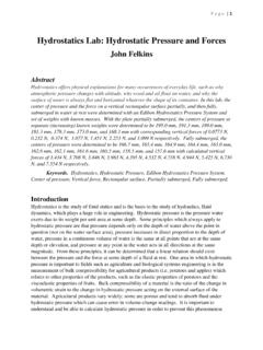
1 Hydrostatic Pressure By John Fuller Fluid Mechanics Lab Wednesday(1-345pm) Group member: Abdur Rahaman Abstract The objective of this lab is to determine the Hydrostatic thrust acting on a plane surface immersed in water when the surface is partially submerged or fully submerged. Also to determine the experimental center of Pressure , and the theoretical center of Pressure for each of the trials performed. Introduction Hydrostatic Pressure is, the Pressure exerted by a Fluid at equilibrium due to the force of gravity.
2 A Fluid in this condition is known as a Hydrostatic Fluid . So our Hydrostatic Pressure lab was to determine the Hydrostatic Pressure of water on a flat surface. Adding weight and then filling the tank with water to the point where the apparatus was in equilibrium. so we can calculate the force on the flat surface using the given equations. Physical Setting All procedures for the orifice and free jet flow lab were performed at UAA in the ANSEP building in room 102. the room is equipped with the testing apparatus for this lab.
3 The building is at room temperature and is at standard atmospheric Pressure . Experimental Procedures Equipment The equipment required for the testing of this lab is: The F1-12 Hydrostatic Pressure Apparatus F1-10 Hydraulics Bench (water source) Graduated Cylinder Procedure - Equipment set-up Position the empty F1-12 flotation tank on the Hydraulics Bench, then adjust the screwed feet until the built-in circular spirit level indicates that the tank is level in both planes. Position the balance arm on the knife edges and check that the arm is free to swing.
4 Then find the empty weight hanger in the groove at the end of the balance arm. Move the counter-balance weight until the balance arm is horizontal by the checking that the central index mark on the beam level indicator. Procedure - Taking a Set of Results The first part of this lab test was completed by adding mass to the balancing arm with the mass hanger in 50 gram increments until the tank is full. Water was then added to the tank to level the balancing arm by increasing the force on the plane surface. The height of the water measurements were recorded along with the added mass.
5 The second part of this lab was completed by starting with a full tank and removing mass. The height of the water and added mass were recorded as in the first part of the lab. Results From the data collected the Hydrostatic Pressure and distance to the centre of Pressure can be calculated for both the partially submerged and fully submerged plane surface. Once this is done the theoretical Hydrostatic Pressure and distance to the centre of Pressure can be calculated. From this one could compare the theoretical values to the actual values measured.
6 The percent difference is then determined. The percent difference between the measured and theoretical forces was almost nearly zero for all increments. We did have some discrepancy between the measured and theoretical depths to the center of Pressure . The percent error of depth to the center of Pressure ranged from to Following is the graphs for the Hydrostatic Pressure and the distance to the centre of Pressure for both partially and fully submerged. Sample Calculations Experimental equations used for face fully submerged: Face Fully Submerged Diagram M = Fh Fh = WL = mgL Sample: = ( )( )( )/( = N Sample: ( )( )/(1000)( )( )[ ( ^2)]= m Experimental equations used for face partially submerged: Partially Submerged Face Diagram M = Fh Fh = WL = mgL Sample.)
7 = 2( )( )/(1000)( )( ^2) = Discussion The force applied in the system vertical face of buoyant material counter acts the mass added to the hanging arm. so we know that if we move away from the sea level, the Pressure will change either with air or water. So in our experiment also change in Pressure because of the weight of the water above and buoyant forces clearly show the properties of water. The water Pressure was so high that we add the mass 50 g to 450g even still quadrant was able to support it in static equilibrium.
8 So the idea let us to believe that the curved area allows for a larger surface with which the water can act upon for less change in depth. This would explain such a large jump in force applied after breaking the upper plane of the vertical face. Conclusion The graphical analysis of our lab shows that a linear relationship between Hydrostatic force and Average Depth for the Partially Submerged and the graph of Hydrostatic force and Average Depth for Fully Submerged is also linear. Our Theoretical force compared to the measured force were nearly identical with a percent errors of ^-14%.
9 The error in the distance to the centre of Pressure compared to the theoretical was outrageously high with a percent error of The graphical analysis showed a linear relationship between Hydrostatic force and Average Depth for only fully submerged. The graph of Hydrostatic force and Average Depth for partially submerged is not perfectly linear. References Armfield Limited, 2002, Instruction Manual F1-16,; Ringwood, Hampshire. BH24 1DY England Appendices