Transcription of I. ET125 electric cylinder features - Parker Hannifin
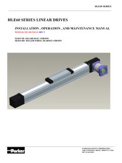
1 ET125 MAINTENANCE MANUALThis guide contains maintenance instructions, replacement parts information, andinformation on various of ContentsI. ET125 featuresII. General maintenance proceduresIII. Exploded viewsIV. Parts listV. Torque tableVI. Motor coupler and pulley spacingVII. Timing belt tensioningI. ET125 electric cylinder features : Ground and polished precision stainless steel rod Bearing support on front end of ball screw Combination lip and wiper seal Extra length rod bearing Polyurethane bumper on end cap Precision anti-rotate drive nut bearings Tapered roller bearings on screw Anti-friction ball bearing nut Extruded and anodized aluminum body Integral switch grooves on all four sides High quality flexible coupling Internal magnet (sensing target for switches) High performance servo motors Produced to hard metric ISO standardsDrives available.
2 Brushed servos User provided (see specifications at the end of this guide)Controls:Microprocessor based system interfaces with computers and programmable APEX 640 motor with GEMINI drive from Compumotor run on the 6K software HJ155 and HJ190 motors with the COMPAX 3500M drive/controller run on the Servo-managersoftware from General Maintenance ProceduresCleaningClean cylinder body, head, etc., using a clean cloth. Use only a mild, non-corrosive cleaning agent. Remove any sludge, deposits, or other foreignsubstances from the surface of the : Do not use high-pressure wash down or steam-lance type cleaningsystemsLoctiteUse precautions contained with Loctite or any other adhesive used in procedureBall nutThe ball nut will be shipped from the factory pre-lubricated, however in order toassure proper operation of the cylinder additional lubrication is necessary.
3 Therecommended lubricating frequency is 5 to 6 times over the estimated life of theunit. The recommended lubrication is the Thomson Linear Lube. The lubricationfitting and access hole are provided in the 12 o clock position as standard unlessspecified differently in the part number is the procedure to be followed when re-lubricating the ball nut:Remove the plug (67) from the cylinder body (29). Stroke the cylinder until thelubrication fitting (64) is directly below the hole in the cylinder body. Wipe thefitting with a clean rag. Apply the lubrication until it begins to protrude out fromunder the ball nut bearingsThe taper roller thrust bearings in the rear end cap (7) are pre-lubricated at thefactory upon assembly.
4 Additional lubrication of these bearings is alsorecommended with a lubrication fitting (64) being provided in the cylinder endcap. The recommended lubrication is the Molygrease. This lubrication should bedone 3 to 4 times over the actuator life. The lubrication fitting for the thrustbearings is provided standard in the 3 o clock Exploded viewsAll parts in the following exploded views can be obtained through your Parker AutomationDistributor or through the Automation actuator 1 Basic actuator AssemblyDrawing 2 Inline AssemblyDrawing 3 Parallel AssemblyDrawing 4 Brake AssemblyIV. Parts listET SERIES PARTS LIST125 ITEMDESCRIPTIONQTYPART Bearing1RA368-703 Bumper2ET125M014 Washer1ET125M035 Snap Ring2NA6 Rod Seal1RS453-707 End Cap-Standard1ET125E027 TEnd Cap-Trunnion Mount1ET125E02T8 Screw Support Bearing2RA3999 Washer1ET125M0210 Drive Screw1 TSBM**T**11 Bearing Locknut1B897512 Cap Screw1NA13 Sleeve1NA14 Screw End Bearing1ET125R0615 Washer1ET125R0916 Elastic Locknut1B312217 Nut Retainer1ET125R0318 Roller Cover3ET125 RCA19 Bearing3ET125 RCA20 Snap Ring3NA21 Bearing Retainer3ET125R0422 Flat Head Cap Tip Set Rod1ET125R01-**26 MCylinder Rod End - M1ET125R0526 FCylinder Rod End
5 - F1ET125R1227 MJam Nut - Body1ET125C**30 Cap Screw (in line only) Rod Bolt4B8805-M12-08332 Tie Rod Nut8125-2701533 LKey-Inline1B8534M8-2033 PKey-Parallel1B8534M10-5033 BKey-Brake1B8534M6-3034 Coupler End Fitting - HJ190 Motor1 RGSM383810 Coupler Sleeve1 RGS3898 Coupler End Fitting1 RGSM38300837 Gasket2ET125M0538 Motor Adapter Flange - HJ190 Motor1ET125E0439 Cap Frame Motor Flange1ET125E1342 Flat Head Cap Screw4N/A43 Trunion Mount2ET125E0344 Parallel End Cap1ET125E0645 Pulley - No Flange1ET125P02-34M351046 Pulley - Double Flange1ET125P01-34M381047 Timing Belt1B8868-50-8048 Parallel Mount End Cap1ET125E0749 Tie Rod Bolt4B8805-M12-20850 Parallel Bearing
6 Plate1ET125E1051 Parallel Bearing Plate Gasket1ET125M0852 Socket Head Cap Motor Flange Pl - HJ1901ET125E1454 Parallel housing & motor transition gasket1ET125M0955 Flanged & ribbed M12 SHSS2w/pulley59 SHCS-APEX 640 In Frame Motor In Line1ET125M11 Gasket-155 Frame Motor In Line1ET125M10 Gasket-190 Frame Motor In Line1ET125M3161 Lockwasher-142 Frame Motor4 ESF1110 Lockwasher-155 Frame Motor4 ESF111062 Key1w/motor64 Zerk fitting2RF40765 Spacer2ET125M3266 Wave spring2B897867 cylinder plug1ET125M3368 Shaft Key1B8534M8-1669 Shaft Key2B8534M10-5070 Dowel pin2 DPM-C00601671 Gasket1ET125M3072 Intermediate plate1ET125E5073 Bearing shaft1ET125R1174 Bearing6204 Peer75 Set Tite Seal1ET125M3580 Gasket1ET125M0581 Intermediate plate1ET125E2082 Stud4B8805-M12-20883 Key1w/brake84 Set screw2w/brake85 Brake SprocketN/A86 Gasket1ET125M1687 Brake Housing1ET125E3388 Flat Head Cap Series Timing belts & pulleysModelDriveDrivenBeltETB125-**AK1* *ET125P01-34M3810ET125P02-34M3510B8868-5 0-80 ETB125-**AH1**ET125P01-34M3210ET125P02-3 4M3510B8868-50-80 ETB125-**A81**ET125P01-34M2408ET125P02-3 4M3510B8868-50-80 ETB125-**AD1**ET125P01-34M4012ET125P02-3 4M3510B8868-50-80 Inline Series CouplerModelScrew CouplerMotor
7 CouplerSpiderETB125-**LK1**RGSM383510 RGSM383810 RGS3898 ETB125-**LH1**RGSM383510 RGSM383210 RGS3898 ETB125-**L81**RGSM383510 RGSM382408 RGS3898 ETB125-**LD1**RGSM383510 RGSM384012 RGS3898V. Torque tableThis table provides torque specifications for all items requiring specific torque values. Whenassembling parts, make sure to use the recommended torque value listed in this table. If a torquevalue is not listed, use industry standard torque for the fastener/metal SpecificationsDescriptionItem Number(s)N-mft-lbsRod Assembly17,25,26204150 Roller Retainer FHSCS222418 Elastic Locknut1610275 Bearing Ret. Locking SHSS122317 cylinder Tie Bolts31,32,30136100 Coupler End SHCS343929 Motor Adapter SHCS397757HJ190 Motor SHCS42,5910980 Apex 640 & HJ155 Motor SHCS42,597757 Parallel Flange Ribbed HHCS55136100 Parallel Cover SHCS527757 Drive Pulley SHSS562317 Ball nut & ET125R03 assembly1710980 Carriage Retainer SHSS242317 Lubrication Fitting64107 Brake Pulley SHCS901612 Brake Housing FHSS882317 Brake Cover Plate BHSCS93107 NOTE: This item number is the number used in the parts listing as well as anymaintenance tasks contained in this Motor coupler and pulley spacingPROCEDURE1.
8 Determine type of motor (inline or parallel).2. Referring to the appropriate illustration and specification table, assemble coupler or pulley tomotor. Make sure to measure the A dimension from the mounting face of the motor. Do notmeasure off of the pilot. Assemble and tighten set screw with Loctite Make sure to torque motor mounting hardware as necessary (if applicable).MotorParallel pulley"A" (mm)Inline coupler"A" (mm)APEX 640 Belt Tensioning Procedure1. Remove the rubber plug (76) in the back of the parallel housing plate (50) and back the M8 SHSS (75) off theflat of the bearing shaft (73).2.
9 Then remove the four socket head cap screws (52), the parallel bearing plate (50), and the gasket (51) out of theparallel Loosen the four flanged hex head cap screws (55). Loosen just enough to allow motor to move belt (47) tension. The correct deflection for the belt with finger pressure is mm. With belt tension toola. Attach belt tension tool assembly (shown below) to mounting plate (53). Support the motor in therear and then turn adjustment screw as required to properly tension the timing belt. Then tightenthe flanged hex head cap screws (55). for proper belt tension. Without belt tension toola.
10 Mount or hold the actuator Then lift up on the motor evenly until the belt has the proper tension. Tighten down the flangedhex head cap screws (55).c. Check for proper belt inspect for proper seating of belt teeth in pulley the four flanged hex head cap screws (55). (Refer to the torque values chart located earlier in thissection.)7. Place the gasket (51) and parallel bearing plate (50) onto the parallel housing (44) with the bearing shaft slidinginto the plate. Orient the bearing shaft and tighten the set screw onto the flat of the bearing up on the parallel bearing plate (50) and keep pressure on this plate as you torque the four button head capscrews (52).
