Transcription of I56-3111-012 CO1224T/CO1224TR Carbon …
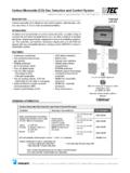
1 CO1224T/CO1224 TRCarbon monoxide DetectorINSTALLATION AND MAINTENANCE INSTRUCTIONS3825 Ohio Avenue, St. Charles, Illinois 601741-800-SENSOR2, FAX: SpecificationsSystem Voltage Nominal: 12/24 VDC Min: 10 VDC Max: 33 VDCAvg. Standby Current: 20 mAMax Alarm Current: 40 mA (75 mA test)Alarm Contact Ratings: 30 VDC @ ATrouble Contact Ratings: 30 VDC @ AAudible Signal (temp 4 tone): 85 dBA min. in alarm (at 10ft)Max. Start-up Capacitance: 20 uFPhysical SpecificationsOperating Temperature Range: 0 to 40 C (32 to 104 F)Operating Humidity Range: 22 90% %RHDiameter: Height: Weight: 7 ozWire Gauge Acceptance: 14-22 AWGNOTICE: This manual shall be left with the owner/user of this equipment.
2 This product is intended for use in ordinary indoor DESCRIPTION Listed to standard 2075 Round shape allows for mounting in aesthetically demanding areas Six-wire, system monitored Optional CO detector replacement plate for previously installed detectors Local sounder Low current draw Alarm relay, Form C Trouble relay, Form A Dual LED s Test/Hush button SEMS wiring terminals Mount to single gang electrical box or surface mount to wall or ceiling Optional drywall anchors includedTABLE 1. DETECTOR OPERATION MODES: OPERATION MODEGREEN LEDRED LEDSOUNDERN ormal (standby)Blink 1 per minuteOFFOFFA larmOFFTemp 4*patternTemp 4* patternAlarm TestOFFTemp 4 patternTemp 4 patternRealTest ModeBlink 1 per secondOFFTemp 4 pattern(after CO is sprayed)End of LifeOFFOFFOFFCO TroubleOFFB link 1 per minuteOFFP ower Loss/Cell FaultOFFOFFOFFA larm Test: Will send alarm signal to feature/Alarm Silence: If required, the audible alarm can be silenced for 5 minutes by pushing the button marked Test/Hush.
3 The red alarm light will continue to flash in temp-4 pattern. If Carbon monoxide is still present after the 5 minute hush period, the audible alarm will sound. The hush facility will not operate at levels above 350 ppm (parts per million) Carbon Alarm Silence: Alarm will automatically silence after about 20 sec-onds of alarm from spraying canned CO into the detector. Alarm Reset: Alarm automatically resets after CO has cleared from the sensor. Trouble feature: When the sensor supervision is in a trouble condition ( such as a sensor that has been tampered with, or the cell itself has prema-turely dried out due to environmental conditions, etc.)
4 , the detector will send a trouble signal to the panel. The detector must then be replaced. The green LED turns off and the red LED blinks every minute when the detector is in trouble. End of Life Timer feature: When the detector has reached the end of its life, the trouble contact will open. This indicates that the CO sensor inside the detector has passed the end of its life and must be replaced. This detector s lifespan is approximately ten years from the date of manufacture. The green LED turns off when the detector is in trouble. Periodically check the Replace by sticker located under the detector cover.
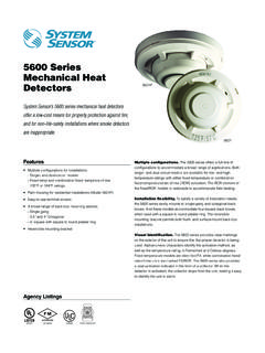
5 The detector must be replaced by this date. Refer to Detector Replacement on page UL 2075, it is mandatory that a trouble signal be sent to the panel upon CO cell trouble or cell end of life. Refer to Figure 4 for wiring of the trouble monoxide /SMOKE ALARMLOCATION FOR MULTI-LEVEL RESIDENCE S0295-01 FIGURE 1. ALARM LOCATION DIAGRAM: 1 I56-3111-012 10-28 installation GUIDELINESC eiling: Detector should be at least 12 inches from any : Detector should be at least as high as a light switch, and at least six inches from the ceiling.
6 Do not install in any environment that does not comply with the detec-tor s environmental specifications Install in accordance with NFPA 720 the Standard for the installation of Carbon monoxide (CO) Detection and Warning Equipment As of 2009, NFPA 720 defines standards for both commercial and resi-dential installations of CO detectors . If the installation can be interpreted as a commercial application, consult the section of NFPA 720 that out-lines commercial applications. For example, Chapter states that Carbon monoxide detectors shall be installed in accordance with manufacturers published instruc-tions in the following locations: (1) On the ceiling in the same room as permanently installed fuel burn-ing appliances (2) Centrally located on every habitable level and in every HVAC zone of the building If the installation can be interpreted as residential, consult the section of NFPA 720 that outlines residential applications.
7 For example, chapter states that Carbon monoxide alarms or detectors shall be installed as follows: (1) Outside each separate dwelling unit sleeping area in the immediate vicinity of the bedrooms (2) On every level of a dwelling unit, including basements (3) Other locations where required by applicable laws, codes or standardsMOUNTINGThe CO1224T/CO1224TR can be ceiling-mounted or wall-mounted:1. To a single gang Direct mount to ceiling or to wall using drywall WIRING installation GUIDELINESAll wiring must be installed in compliance with the NFPA 70, National Electrical Code, applicable state and local codes, and any special requirements of the local Authority Having Jurisdiction (AHJ).
8 Proper wire gauges should be used. The conductors used to connect Carbon monoxide detectors to the alarm control panel and accessory devices should be color-coded to reduce the likelihood of wiring errors. Improper connections can prevent a system from responding properly in the event of a CO. The screw terminals in the mounting base will accept 14-22 gauge wire. Wire connections are made by stripping approximately 1 4 of insulation from the end of the feed wire, inserting it into the proper base terminal, and tightening the screw to secure the wire in place. Do not put wires more than 2 gauge apart under the same clamping : This product does not have a local audible trouble signal, and may fail without supervision if trouble loop remains : Gas detectors on a zone that is bypassed may not signal a trouble condition.
9 Do not bypass zones used for gas diagrams located on page 4, Figure power from alarm control unit or initiating device circuits before in-stalling Using a small, flat head screw driver, push in the small tab located on the underside of the detector. Once the snap is loosened, lift the bottom end of the cover up and unhinge the top to remove the Wire the detector base screw terminals per Figure Screw the base of the detector onto a single gang electrical box, or to the surface of the wall or ceiling. Use the hardware included in the packaging. 4. If mounting with the System Sensor replacement plate model CO-PLATE*: * Hold replacement plate over desired mounting area.
10 * Use hook feature to hold CO1224T onto the replacement plate. * Mount detector and plate together using hardware provided with the CO1224T. 5. Hinge the top portion of the cover onto the base; with the cover at a 45 degree angle, fit the hinges into the slots of the Push the unhinged bottom portion of the cover down until it snaps into After all detectors have been installed, apply power to the alarm control Test each detector as described in Testing. 9. Notify the proper authorities that the system is in dust particles can enter the detector. System Sensor recommends the installation of detectors after construction or any other dust producing activ-ity.