Transcription of ICC-ES Evaluation Report ESR-3517 - Barsplice …
1 ICC-ES Evaluation Reports are not to be construed as representing aesthetics or any other attributes not specifically addressed, nor are they to be construed as an endorsement of the subject of the Report or a recommendation for its use. There is no warranty by ICC Evaluation Service, LLC, express or implied, as to any finding or other matter in this Report , or as to any product covered by the Report . Copyright 2020 ICC Evaluation Service, LLC. All rights reserved. Page 1 of 5 ICC-ES Evaluation Report ESR-3517 Reissued October 2020 This Report is subject to renewal October 2022. | (800) 423-6587 | (562) 699-0543 A Subsidiary of the International Code Council DIVISION: 03 00 00 CONCRETE Section: 03 21 00 Reinforcing Steel Report HOLDER: Barsplice PRODUCTS INC. Evaluation SUBJECT: ZAP SCREWLOK TYPE 2 AND FX MECHANICAL SPLICE SYSTEMS FOR SPLICING STEEL REINFORCING BARS Evaluation SCOPE Compliance with the following codes: 2015 International Building Code (IBC) Other Codes (see Section ) For Evaluation for compliance with codes adopted by the Los Angeles Department of Building and safety (LADBS), see ESR-3517 LABC Supplement.
2 Property evaluated: Structural USES General: The Zap Screwlok Type 2 and FX Mechanical Splice Systems are used as mechanical splices of deformed steel reinforcing bars in reinforced concrete construction. Zap Screwlok Type 2 Mechanical Splice System: The Zap Screwlok Type 2 system complies with Section of ACI 318-14 (as referenced in Section of the 2015 IBC) for use as tension and compression mechanical connections of ASTM A615 Grades 40, 60, and 75, or ASTM A706 Grade 60 deformed steel reinforcing bars sizes No. 4 through No. 11, No. 14, and No. 18. This system, when used to splice ASTM A615 Grade 40 and 60 bars and ASTM A706 Grade 60 bars, complies with the Type 1 and Type 2 mechanical splice requirements of Section of ACI 318-14, and is for use where Type 1 or Type 2 mechanical splices are specified by the IBC and ACI 318. This system, when used to splice ASTM A615 Grade 75 bars, complies with the performance requirements of Section of ACI 318-14 for Type 1 mechanical splices, except that the use of this system to splice Grade 75 bars for special seismic applications is outside the scope of this Evaluation Report since Sections and of ACI 318-14 specify a maximum steel grade of 60 for reinforcing bars used for special seismic applications.
3 Zap Screwlok FX Mechanical Splice System: The Zap Screwlok FX system complies with Section of ACI 318-14 (as referenced in Section of the 2015 IBC) for use as tension and compression mechanical connections of ASTM A615 Grade 75 and 80, or ASTM A706 Grade 80 uncoated deformed steel reinforcing bars sizes No. 11, No. 14, and No. 18. This system, when used to splice No. 11, No. 14, and No. 18 of ASTM A615 Grade 75 bars, or No. 11 and No. 14 of ASTM A615 Grade 80 bars, or No. 11, No. 14, and No. 18 of ASTM A706 Grade 80 bars, complies with the performance requirements in ACI 318-14 Sections and for Type 1 and Type 2 mechanical splices and is for use where Type 1 or Type 2 mechanical splices are specified by ACI-318 and IBC. This system, when used to splice ASTM A615 Grade 80 No. 18 bars, complies with the Type 1 mechanical splice performance requirements of Section of ACI 318-14, and is for use where Type 1 mechanical splices are specified by the IBC and ACI 318.
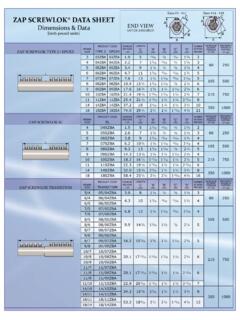
4 The use of this system to splice Grade 75 and Grade 80 bars for special seismic applications is outside the scope of this Evaluation Report , since ACI 318-14 Sections and specify a maximum steel grade of 60 for reinforcing bars used for special seismic applications. DESCRIPTION General: Zap Screwlok Type 2 Mechanical Splice System: The Zap Screwlok Type 2 Mechanical Splice System is available in two types: Standard splice system and Transition splice system. Each Standard splice system consists of a Standard splice assembly and two equal size reinforcing bars, sizes No. 4 through No. 11, with a single row of screws, or sizes No. 14 or No. 18, with double rows of screws (see Table 1 and Figure 1). Each Transition splice system consists of a Transition splice assembly and two reinforcing bars of different sizes, No. 4 through No. 11, using one row of screws (see Table 2 and Figure 1). Zap Screwlok FX Mechanical Splice System: The Zap Screwlok FX Mechanical Splice System is available in Standard splice type and is used to splice two equal size reinforcing bars.
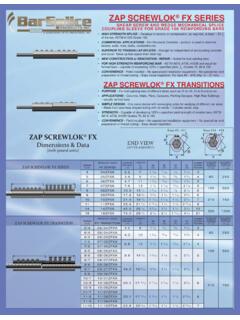
5 For reinforcing bar size No. 11, a single row of screws are used, and for reinforcing bar sizes No. 14 or No. 18, double rows of screws are used (see Table 3 and Figure 1). Materials: General: Each Zap Screwlok Type 2 and FX Mechanical Splice assembly consists of a shaped steel sleeve with converging sides, an optional central stop pin ESR-3517 | Most Widely Accepted and Trusted Page 2 of 5 that establishes the proper insertion depth of the connected reinforcing bars, and a series of steel screws with cone-shaped points. The sleeve is produced from steel conforming to ASTM A519 Grades 1018 to 1026, with minimum yield strength of 36,000 psi (248 MPa) and a minimum tensile strength of 60,000 psi (420 MPa). The screws are produced from steel conforming to ASTM A322 Grade 4140. Zap Screwlok Type 2 Mechanical Splice System: Each Zap Screwlok Type 2 system is used for splicing two deformed, reinforcing bars having either equal or unequal diameters and having a yield strength of 40 ksi (280 MPa), 60 ksi (420 MPa), or 75 ksi (520 MPa) for ASTM A615 Grade 40, 60, or 75, respectively, or 60 ksi (420 MPa) for ASTM A706 Grade 60.
6 The reinforcing bars, except for #14 and #18, may be coated in accordance with A767 (zinc-coated) or A775 (epoxy-coated). Dimensional data is presented in Tables 1 and 2 for the Zap Screwlok Type 2 Standard and Transition Splice Systems respectively, and is illustrated in Figure 1. Zap Screwlok FX Mechanical Splice System: Each Zap Screwlok FX system is used for splicing two uncoated deformed reinforcing bars having equal diameters and a yield strength of 75 ksi (520 MPa), 80 ksi (550 MPa) for ASTM A615 Grade 75 and 80 respectively, or 80 ksi (550 MPa) for ASTM A706 Grade 80. Dimensional data is presented in Table 3 for the Zap Screwlok FX Standard Splice System and is illustrated in Figure 1. DESIGN AND INSTALLATION General: The Zap Screwlok Type 2 and FX Mechanical Splice Systems are installed at the jobsite. These systems allow pre-bent and pre-tied reinforcing bars to be spliced in place without having to rotate the bar.
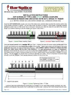
7 All splice assembly components and reinforcement to be spliced must be clean and free from loose rust, oils, and other foreign matter. Water must also be removed from the sleeves prior to installation. First, one of the reinforcing bars to be spliced is inserted into one sleeve end to the center stop. The screws are then tightened from the sleeve end inward towards the center of the sleeve. The reinforcing bar is engaged to the sleeve by indenting the bar surface and wedging the bar into the converging sleeve sides through tightening of the screws. Screws must be tightened to the corresponding torque values shown in Tables 1, 2, and 3, as applicable, at which point the screw heads shear off. After the first bar is secured, the other reinforcing bar is inserted into the opposite sleeve end to the center stop. The screws are then tightened in the same manner as for the first bar, from the end of sleeve inward towards the center of the sleeve until the screw heads shear off.
8 For the splices with two rows of screws at each side of the sleeve: first, one of the row of screws must be tightened as described above, followed by the entire second row of screws. If the splice sleeve is specially supplied, without a center stop, or if the center stop is removed to facilitate construction, one half of the splice length (L/2) must be measured and marked on the reinforcing bar before inserting it into the splice. Once the splice is placed so that the bars are at the proper insertion, and the screws on the first reinforcing bar have been tightened down and heads twisted off, the second reinforcing bar can then be secured as described above. All measurements pertaining to minimum bar spacing distance and concrete coverage requirements described in the IBC and ACI 318, must be measured from the outside of the sleeves. Zap Screwlok Type 2 Mechanical Splice Systems The use of this splice system must comply with Section of this Report .
9 Zap Screwlok FX Mechanical Splice Systems The use of this splice system must comply with Section of this Report . Special Inspection Special inspection must be provided at the jobsite as required by Section 1705 of the 2015 IBC. In addition to verifying placement of steel reinforcing bar splices, the special inspector must verify the grade and size of reinforcing bars, reinforcing bar embedment, spacing, concrete cover, splice system identification, field preparation of components, and assembly of the components resulting in the spliced bars. CONDITIONS OF USE The Zap Screwlok Type 2 and FX Mechanical Splice Systems for splicing steel reinforcing bars, as described in this Report , comply with, or are suitable alternatives to what is specified in the code indicated in Section of this Report , subject to the following conditions: The splice assemblies must be identified, designed and installed in accordance with the applicable code, the manufacturer s instructions, and this Report .
10 In the event of conflict between this Report and the manufacturer s instructions, this Report governs. Special inspection must be provided in accordance with Section of this Report . The minimum concrete cover and spacing between spliced bars must be in accordance with the ACI 318-14 (IBC 2015) and must be measured from the outer surface of the splices. Splice locations must comply with the applicable ACI 318-14 (IBC 2015) requirements and must be noted on plans approved by the code official. For structures regulated by Chapter 18 of ACI 318-14 (as required by 2015 IBC Section ), to splice deformed reinforcing bars resisting earthquake-induced flexure, axial force, or both, in special moment frames, special structural walls, and all components of special structural walls including coupling beams and wall piers, with the Zap Screwlok Type 2 mechanical splice system, mill certificates for reinforcing bars must be submitted to the code official as evidence that the steel reinforcing bars comply with ACI 318-14 Sections and The use of Zap Screwlok Type 2 and FX mechanical splice systems must comply with Sections and , respectively.