Transcription of ICOM IC-706mkII - User manual
1 INSTRUCTION MANUALi706MK GHF/VHF/UHF ALL MODE transceiver This device complies with Part 15 of the FCC rules. Operation is sub-ject to the following two conditions: (1) This device may not causeharmful interference, and (2) this device must accept any interferencereceived, including interference that may cause undesired DEFINITIONSPRECAUTIONSIMPORTANTRead this instruction manual carefullybefore attempting to operate the this instruction manual . This instructionmanual contains important safety and operatinginstructions for the HIGH VOLTAGE! NEVER attach an antenna or internal antenna connector dur-ing transmission. This may result in an electrical shockor AC to the [ ] socket on thetransceiver rear panel. This could cause a fire or ruinthe more than 16 V DC, such as a 24 Vbattery, to the [ ] socket on the transceiverrear panel.
2 This could cause a fire or ruin the metal, wire or other objects touch anyinternal part or connectors on the rear panel of thetransceiver. This will cause electric the transceiver to rain, snow orany allow children to play with the using or placing the transceiver in areas withtemperatures below 10 C (+14 F) or above +60 C(+140 F). Be aware that temperatures on a vehicle sdashboard can exceed 80 C, resulting in permanentdamage to the transceiver s front panel if left there forextended placing the transceiver in excessively dustyenvironments or in direct placing the transceiver against walls or puttinganything on top of the transceiver . This will obstructheat mobile operation, DO NOToperate the trans-ceiver without running the vehicle s engine. Whentransceiver power is ON and your vehicle s engine isOFF, the vehicle s battery will soon become sure the transceiver power is OFF before start-ing the vehicle.
3 This will avoid possible damage to thetransceiver by ignition voltage maritime mobile operation, keep the transceiv-er and microphone as far away as possible from themagnetic navigation compass to prevent CAREFUL!The heatsink will become hot whenoperating the transceiver continuously for long CAREFUL!If a linear amplifier is connected, setthe transceiver s RF output power to less than the lin-ear amplifier s maximum input level, otherwise, the lin-ear amplifier will be Icom microphones only (supplied or optional).Other manufacturer s microphones have different pinassignments and connection to the IC-706 MKIIG maydamage the signals may be heard on some will occur as a result of circuit onlyCaution:Changes or modifications to this transceiver , notexpressly approved by Icom Inc., could void your author-ity to operate this transceiver under FCC explicit definitions described below apply to thisinstruction injury, fire hazard or electricshock may damage may disregarded, inconvenience only.
4 No riskof personal injury, fire or electric OF CONTENTSIMPORTANT .. iPRECAUTIONS .. iEXPLICIT DEFINITIONS .. iTABLE OF CONTENTS .. iiUNPACKING .. ii1 PANEL DESCRIPTION .. 1 8 Front panel .. 1 Function switches .. 3 Rear and side panels .. 5 Function display .. 7 Microphone (HM-103) .. 82 INSTALLATION AND CONNECTIONS .. 9 14 Unpacking .. 9 Grounding .. 9 Antenna .. 9 Installation .. 10 Required connections .. 11 Advanced connections .. 12 Power supply connections .. 13 External antenna tuners and linear amplifier .. 143 FREQUENCY SETTING .. 15 19 When first applying power (CPU resetting) .. 15 Initial settings .. 15 VFO description .. 16 Frequency setting .. 17 Mode selection .. 194 RECEIVE AND TRANSMIT .. 20 38 Functions for receive .. 20 Functions for transmit .. 25 Split frequency operation .. 29 Tone squelch operation.
5 31 Tone scan operation .. 31 One-touch repeater .. 32 Auto repeater function .. 32 Functions for CW .. 33 Functions for RTTY .. 35 Packet operation .. 37 SWR .. 385 MEMORY AND SCAN OPERATION .. 39 44 Memory channels .. 39 Memory channel selection .. 39 Memory clearing .. 39 Memory/call programming .. 40 Frequency transferring .. 41 Memory names .. 41 Memo pads .. 42 Scan types .. 43 Preparation .. 43 Programmed scan operation .. 44 Memory scan operation .. 44 Select memory scan operation .. 44 Priority watch .. 446 REMOTE JACK (CI-V) INFORMATION .. 45 467 SET MODE .. 47 55 General .. 47 Quick set mode items .. 48 Initial set mode items .. 508 MAINTENANCE .. 56 Fuse replacement .. 56 Memory backup .. 56 Cleaning .. 569 TROUBLESHOOTING .. 57 5810 OPTIONAL INSTALLATIONS/SETTINGS .. 59 62 Opening the transceiver case .. 59 UT-102 VOICE SYNTHESIZER 59 CR-282 HIGH-STABILITY CRYSTAL 60 IF filters.
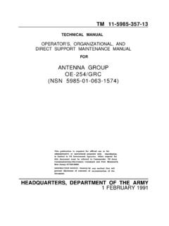
6 60 UT-106 DSP RECEIVER 61 MB-72 CARRYING 61 AT-180 internal switch description .. 6211 INTERNAL VIEWS .. 6312 OPTIONS .. 64 6513 SPECIFICATIONS .. 6614 MENU GUIDE .. 67 68iiUNPACKINGA ccessories included with the IC-706 power cable* ..1wHand microphone (HM-103)..1eSpare fuse (30 A) ..2rSpare fuse (4 A) ..1tRTTY key keyer plug ..1uACC cable ..1iFerrite bead** ..1*OPC-639 for Europe versions (differs from the diagram atleft), OPC-025D for other versions.**Not supplied with some Front panelqPOWER SWITCH [POWER] (p. 15)Turns power ON and OFF. Push momentarily to turn power ON. Push for 2 sec. to turn power GAIN CONTROL [AF] (inner control; p. 15)Rotate clockwise to increase the audio output fromthe speaker; rotate counterclockwise to decreasethe audio output from the GAIN CONTROL/SQUELCH CONTROL[RF/SQL] (outer control; p. 22) Adjusts the squelch threshold level (to mute noisewhen receiving no signal) in all modes.
7 This control can be used for RF gain control toadjust receiver gain manually. RF gain selection can be set in initial set mode (p. 50). RF gain is usable in SSB/CW/RTTY modes DISPLAYS hows the operating frequency, dot matrix indica-tions, selected memory channel, etc. See p. 7 STEP SWITCH [TS] (pgs. 17, 18) Push momentarily to cycle between 1 Hz/10 Hz,programmable and 1 MHz tuning steps. 1 and 10 Hz steps are only available in SSB, CW andRTTY modes; 1 MHz steps are only available in FM,WFM and AM modes. Push for 2 sec. to toggle between 1 and 10 Hzsteps, or; when the programmable tuning steps isindicated, push for 2 sec. to enter programmabletuning step SWITCH [MODE] (p. 19) Push momentarily to cycle through the operatingmodes:USB/LSB CW/CW RTTY/ RTTY FM/WFM/AM Push and hold for 2 sec. to toggle between thefollowing operating modes:USB LSBCW CW RTTY RTTYFM WFM AM FM, INDICATORS [RX]/[TX][RX] lights green while receiving (and squelchopens); [TX] lights red while DIALC hanges the displayed frequency, selects initial setmode items, (BAND) SWITCHES [Y/Z(BAND)] Push to select a band.
8 Can also be used to advance quick set mode items,initial set mode items, etc. Push and hold to scroll through the bands contin-uously.!0 MAIN DIAL TENSION LATCHS elects the main dial tension. 2 positions are available.!1 MICROPHONE CONNECTOR (p. 8)Modular-type microphone connector connects thesupplied microphone (HM-103). The optional OPC-589 can be used to connect an 8-pinmicrophone such as the SM-8 or SM-20, if desired. A microphone connector is also available on the rear11 PANEL DESCRIPTIONHF/VHF/UHF TRANSCEIVERi706MK GAFRIT/SUBMENUF-1F-2F-3 MODEBANDBANDYZTSDISPLAYLOCKRXTXM- !1!2!3!4!5!6!7!8!9@0@2@1!0uCHVFO APOS15537920401060dBUSBM1 SPLA/BA=B21 PANEL DESCRIPTION panel. DO NOT connect 2 microphones simultaneously.!2 LOCK SWITCH [LOCK] Push momentarily to turn the dial lock functionON and OFF. The dial lock function electronically locks the maindial.
9 When the optional UT-102 VOICE SYNTHESIZERUNITis installed (p. 52), push for 2 sec. to havethe frequency, etc. announced. UT-102 operation can be adjusted in initial set mode(pgs. 53, 54).!3 DISPLAY SWITCH [DISP] (p. 68) Push momentarily to select one of the three menusets: M1to M4, S1to S4and G1to G4. Push for 2 sec. to select quick set mode.!4 FUNCTION SWITCHES [F1]/[F2]/[F3] (pgs. 3, 4, 68)Push to select the function indicated in the dotmatrix display above these switches. Functions vary depending on the menu set selected.!5 MENU SWITCH [MENU] (p. 68) Push this switch one or more times to selectmenus within a menu set (M, Sor G), or push toadvance through the quick set mode and initialset mode displays. Push and hold to jump between two differentfunction menu sets.!6 RIT/SUB DIAL SWITCH [RIT/SUB] (p. 20) Push to toggle the RIT or SUB DIAL function ONand OFF initial set mode is used to select thedesired action*.
10 Lights green when the SUB DIAL function is ON;lights red when the RIT function is ON. Use the [M-CH] control to vary the RIT frequency orSUB DIAL frequency (see above). When the RIT function is ON, push for 2 sec. toadd or subtract the shifted frequency to the oper-ating frequency.*Even if RIT is selected in initial set mode, RIT cannot beselected when operating AM, FM or WFM modes.!7 SHIFT CONTROL [SHIFT] (outer control; p. 20)Shifts the center frequency of the receiver s IF pass-band. Rotate the control clockwise to shift the center frequen-cy higher, or rotate the control counterclockwise to shiftthe center frequency lower. When the graphic menu display (G2) is selected, the IFpassband is graphically displayed and changes in accor-dance with the [SHIFT] control (see p. 20).!8M-CH CONTROL [M-CH] (inner control) When the RIT or SUBDIAL functions are OFF,rotate to select a memory channel number (p.)