Transcription of Ignition Installation Troubleshooting …
1 Ignition Installation Troubleshooting Tips/Frequently-Asked Questions Warning: Reversing the red and black Ignition wires will destroy the Ignition module and void the warranty. The Hot-Spark module's red wire connects to positive ( + or 15 on Bosch coil). The black wire connects to negative ( or 1 on Bosch coil). Connect any other wires to the coil in their original positions. This Ignition module is designed for 12V negative ground applications only. Do not connect either of the coil's terminals ( +. or - ) to ground (earth). Voltage, measured at the coil's + terminal, must never exceed volts at any RPM. level. Too much voltage going to the coil's + terminal can cause the Ignition module to overheat and run erratically or fail. Wiring a O ballast resistor between the coil's + terminal and the red HotSpark Ignition module's red wire decreases excess voltage going to the Ignition module, helping to protect the module from over-voltage and voltage/amperage spikes.
2 Customers occasionally return Ignition kits to us that have failed. In the great majority of cases, it is the result of misuse, reversed or improper wiring or problems with the vehicle's electrical system ( , low voltage) and not the fault of the Ignition kit. Here are the most common causes of failure (in the following order): 1. Key is left on without the engine running. If the engine happened to stop in a position similar to points closed, the Ignition module will continue charging the coil without the coil's discharging, resulting in excessive heat buildup in the coil, which can fry the Ignition module and/or coil. As a general rule, don't leave the Ignition switch in the ON position for more than a minute or so, without the engine running. If the engine happened to stop in a position similar to points open, the Ignition module/coil circuit would be open, no current would flow, and there would be no damage to the electronics.
3 2. Coil Required: Do not use a low-resistance coil that does not have the minimum primary resistance required by the Ignition module, as stated in the instructions (minimum ohms for 4- and 6-cyl or ohms for 8-cyl, assuming a 12-Volt electrical system). The coil resistance regulates the current in the Ignition module/coil circuit. Too little coil primary resistance resistance results in too much amperage going to the Ignition module, which can overheat the 2005-2017 HotSpark . electronics. The failure may not happen immediately, but the excess heat will shorten the life of the Ignition module electronics. How long the electronics will last depends on how much heat is generated. It could be a matter of a couple of hours to a few hundred hours, depending on temperature. To measure primary resistance: Label and remove all wires to coil ( + or - ).
4 Using a common digital multimeter in the 200 O mode, cross the red and black leads of the Ohmmeter. Allow 10 seconds or more for the reading to settle and write down the reading. Still in the 200 Ohm mode, measure between coil's + and - terminals. Allow a few seconds for the reading to settle, until it stabilizes. Subtract the previous reading, taken with the leads crossed, to compensate for Ohmmeter's inherent resistance. Do not use a low-resistance coil, such as the MSD or Accel coil; they don't have enough primary resistance for this application. For best performance, the coil should also have 7K Ohms or more secondary resistance (measured from coil's + or terminal to center high tension terminal, in the 20K mode of the Ohmmeter). Ballast Resistor: If the coil's primary resistance is not quite enough or is borderline, you can wire an external ceramic ballast resistor (with to Ohms resistance) between the coil's + terminal and the red HotSpark Ignition wire: 3.
5 Polarity reversed when wiring the Ignition kit ( , wiring the Ignition kit to the + and - terminals of the coil, backwards). This will fry the Ignition module's electronics immediately. The red HotSpark wire should go to the coil's + terminal and the black HotSpark wire should go to the coil's - terminal. Finally, it is possible for an Ignition module to fail on its own, but this is the case in only a very small percent of the Ignition kits that are returned. About 90 per cent of returned Ignition kits usually test to be working perfectly, indicating a problem with the vehicle in which they were installed, improper wiring, bad connections or not setting the timing correctly with a stroboscopic timing light. Of the Ignition modules that have failed, we can usually trace the reason to one of the causes listed above. A few other common Installation problems are: 1.
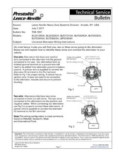
6 Corroded and/or loose ground connection, either at the battery terminal or at the other end of the ground cable, where it makes contact with the vehicle body. Loose wire connections or poorly-spliced wires. The wire grounding the breaker plate, in vacuum-advance distributors, is not connected or has a loose or corroded connection. 2. Magnets in magnet sleeve not aligned vertically with the Ignition sensor, because the distributor shaft is not shimmed properly, the rotor is too tall for the distributor, etc. If the sensor or magnets are too high or low, no signal will result and the engine won't fire. It's possible that the vertical alignment of the magnet sleeve and the Ignition module's sensor is off. Generally, the top of the black magnet sleeve should be slightly above the top of the bottom- most step of the red Ignition module.
7 The distributor shaft should spin freely, without dragging, when the distributor is out of the car, and magnet sleeve, rotor and distributor cap are installed. If the rotor is too tall, about one mm or so can be ground from the bottom of the rotor button, allowing the distributor shaft to spin freely. A belt sander or rough sandpaper on a flat, smooth surface can be used to grind a little off the bottom of the rotor. 3. Distributor shaft height is too high or low, indicating too many or not enough spacing shims are installed in the distributor. Over time, the distributor shaft shims can wear out, causing up-and-down (axial) sloppy shaft movement and misalignment of the sensor and magnet sleeve. If the rotor doesn't extend far enough down to keep the magnet sleeve in place, you may need to use a zip-tie, tightened very snugly, around the distributor shaft, on top of the magnet sleeve, to keep the magnet sleeve in place, to prevent the magnet sleeve from sliding up too far, where the magnets don't align with the Ignition sensor.
8 Many distributors have distributor shafts that may vary in height, depending on the wear, number and thickness of the distributor shaft shims inside the distributor. 2005-2017 HotSpark . A small oval plate and metric hex-head screws may have been included with the Ignition kit in case you need to boost the height of the red Ignition module to align with the magnets inside the magnet sleeve. An O-Ring may have been provided to raise the height of the magnet sleeve, if that is needed instead. Install the O- Ring around the distributor shaft, underneath the magnet sleeve. 4. The voltage, measured at the coil's + terminal, should be near battery voltage, or about + volts. If not, a wire can be run, on a temporary-only testing basis, directly from the battery's + terminal to the red Ignition module's red wire. Do not leave this temporary wire attached for longer than a minute or so, while the engine is not running.
9 Wiring Installation Basics: 1. Begin with a fully-charged battery. Turn on the Ignition switch. With engine not running, using a voltmeter in the 20. Volt DC mode, check that the voltage, measured at the coil's + terminal, is around + volts, about the same as battery voltage. The red voltmeter lead should touch the coil's + terminal while the black voltmeter lead is touching engine ground. If voltage reading is too low or there's no reading, the battery's terminals or ground connection may be corroded and need cleaning. Some vehicles have a resistor wire running from the Ignition switch to the coil's +. terminal. If this resistor wire drops the voltage below 10 volts or so, you may need to run a non-resistor wire from the Ignition switch to the coil's + terminal. Make sure that the Ignition switch terminal to which you connect this wire has power only when the Ignition switch is in the ON position.
10 Or, you can, for temporary testing purposes only, run a wire directly from the battery's + terminal to the Hot Spark Ignition 's red wire and the black Hot-Spark wire to the coil's - terminal. Do not leave the wire from the battery connected to the red Ignition module's red wire for more than a minute or so without the engine running. Neither the coil's - or + terminals should ever be connected to engine ground (earth). 2. Remove the points, condenser and the condenser's wire from the vehicle. To get the Ignition running initially, only these wires should be attached to the coil's + and - terminals: A. +12 volts from the Ignition switch (+12-volt power source) to the coil's + terminal B. Red Hot-Spark wire to the coil's + terminal C. Black Hot-Spark wire to the coil's - terminal. DO NOT touch any +12-volt wire to the coil's - terminal.