Transcription of Impact Load Factors - Rice University
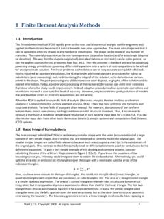
1 Prof. Akin, Rice University Impact load Factors for Static Analysis Often a designer has a mass, with a known velocity, hitting an object and thereby causing a suddenly applied Impact load . Rather than conduct a dynamic analysis an amplified static analysis is used, at least for the preliminary design. In a static stress analysis the static force (or weight of the mass) must be increased by an Impact Factor so as to obtain a good approximation of the maximum dynamic deflection and stress. For hard elastic bodies the Impact Factor, for vertical impacts, is always greater than or equal to two. It is not unusual for the vertical Impact Factor to be more than 10, 100, or more than 1,000. The following figure shows an amplified static load , P, used to estimate the maximum deflection and stress in a beam due to the dynamic response of a cantilever beam having a weight, W, dropped vertically onto it.
2 A static force P approximates the dynamic effects of a falling weight W. In the study of the mechanics of solids, an energy balance approximation is used to estimate the required static load . That approximation assumes that all of the kinetic energy of the moving mass is converted, with an efficiency of , to strain energy in the body. If you assume that no noise, or heat, or inelastic response, and neglect the mass of the struck member then = 1 and the collision is 100% efficient. There are several handbook equations that provide corrections to the elementary theory based on the ratio of the striking mass to the member mass. Those corrections seldom give an efficiency of less than = In the case of a weight dropped vertically from a height, h, the vertical Impact Factor is 2 . = 1 + 1 +.. where is the deflection of the member due to a static force (W) applied at the Impact point in the Impact direction.
3 So, even if h = 0 this factor is equal to two. Similarly, a mass moving horizontally with a velocity of v has an horizontal Impact Factor of 2. = .. where g is the acceleration of gravity. There are handbook equations for the static deflections of bars and beams that can be used to define Page 1 of 13. Prof. Akin, Rice University the corresponding member stiffness , k. In general the static deflection is = / , where k is the stiffness of the member, at the Impact point, in the direction of the Impact . For any object, a finite element static stress analysis can be probed to obtain the static deflection, in the direction of the force, at the point of loading to obtain the value of . Here, the mechanics of materials solutions, finite element simulations, and a TK Solver worksheet will all be used to estimate the Impact Factor for example bars and beams.
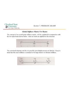
4 The first example (solved by all three methods) is for a weight dropped on the middle of a simply supported beam of rectangular cross . section. The mass of 80 kg is dropped vertically 10 mm from rest onto the center of a horizontal simply supported beam of length m. The beam is steel (E = 200 GPa) with a rectangular cross section area having a width of 60 mm and a height of 30 mm. The first example causes an Impact Factor of about 6. The second example will yield an Impact Factor above 1,200. SolidWorks Finite Element Simulation: The SolidWorks model begins the first example with the cross section, extrudes it to the beam length, and adds vertical split lines to the solid to allow loading at the middle and/or quarter points, and to recover the deflection and stresses there. Generating the symmetric beam member, with split lines The beam member is pinned at the right and supported with rollers on the left.
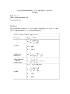
5 The static weight (W =. N) is applied at the center point. Static force applied vertically at beam center After assigning the material properties, the static deflection at the point of loading is obtained: Page 2 of 13. Prof. Akin, Rice University The static deflection at the load point Its value, = mm, is substituted into the above vertical factor equation, with 100 %. efficiency, to yield 2( )1. = 1 + 1 + = so the actual static force needs to be = = ( ) = 4,301 . Applying that load gives a maximum dynamic horizontal fiber stress estimate of about SX = 143 MPa, as seen below. Maximum horizontal stress (143 MPa) is at the center plane top and bottom Of course, since the static model is linear there is no need to re-run the model (unless you want pretty plots). The static maximum fiber stress (SX) of MPa could be multiplied by the vertical Impact Factor to find the dynamic maximum SX stress of 143 MPa.
6 Page 3 of 13. Prof. Akin, Rice University TK Solver Model The TK Solver worksheet begins by writing a set of rules (from mechanics of solids and particle dynamics). The basic TK Solver rules for Impact forces TK rules for five common member structural stiffnesses The initial input variables (below) at the first solution (the first click on the TK lightbulb icon) were incomplete since neither the static deflection nor member stiffness was known. Thus, several rules were not satisfied as indicated by the lack of values in the Output column. Page 4 of 13. Prof. Akin, Rice University Initial velocity results, without the beam stiffness However, the stiffness of a simply supported beam at the center ( load ) point was calculated in the second solve (Lightbulb icon pick) from additional rules by inputting the beam properties, length, and load location (centered m from the support).
7 Additional output of the beam stiffness for input for the member stiffness Page 5 of 13. Prof. Akin, Rice University There were enough inputs provided to calculate the stiffness of three of five typical members including the simply supported beam specified in this example (as seen above). Since the weight is dropped on the center of a simple beam , the value of that beam stiffness (k = N/m) was copied from the output column, of k_simple, and pasted into the input column of k. Then, the next solve gives the desired Impact Factor values for both a horizontal or vertical Impact . Inputting the member stiffness at the load point gives the Impact Factors Now the static deflection ( = 3 ) matches the finite element study well, as does the vertical Impact factor of about (Had the weight been held at the beam surface without toughing it (h = 0) and then released that calculation gives the vertical Impact Factor equal to two, and a zero horizontal value.)
8 In this case, the vertical value was input as the Impact factor and the next solve gave the equivalent force value as = 4,304 , and the dynamic deflection was estimated as about = 6 . The final solve gives the equivalent static force (about 4,300 N). The following figure is an image of a hand solution example taken from the Mechanics of Materials text by A. Pytel and J. Kiusalaas, Thomson, 2003. Those results match the finite element solution, and the TK. Solver solutions, as expected. Page 6 of 13. Prof. Akin, Rice University Page 7 of 13. Prof. Akin, Rice University The second example models a 1 kg mass moving horizontally along a steel (E = 207 GPa) bar 100. mm long with a 10 mm diameter and striking the end of the bar with a velocity of 1 m/sec. (It is taken from Norton, Machine Design, Prentice Hall, 1996.) It is assumed that the correction for the mass of the struck bar reduces the efficiency to = These values were input in the first solve, but the Impact factor cannot be obtained without a member stiffness .
9 So the first solution was to actually find the stiffness of the axial bar, so it could be copied to the member stiffness input. First solve mainly finds the bar member stiffness to be copied Page 8 of 13. Prof. Akin, Rice University Having the member stiffness , the Impact Factors are obtained along with a value of the static deflection . However, the latter (vertical load ) value is only for reference since the Impact is horizontal. The member stiffness yields the horizontal factor to copy An Impact factor defines the equivalent static force and the dynamic displacement This is a very large Impact factor. However, the dynamic deflection still leads to a small elastic strain: = = 100 < Thus, energy loss due to plastic action does not have to be estimated. However, there are corrections published to account for the mass of the bar. Typical additional rules to correct the efficiency for the mass of the member are listed below.
10 It is well known that for bars of a constant diameter the Impact Factor decreases rapidly with increased bar length. The equations for the Impact Factors neglect the mass of the member being struck. There are handbook equations that reduce the efficiency to less than unity by including the mass of the struck member. Some of those corrects are also provided as rules, but they rarely reduce the efficiency below In this case, the bar mass correction only reduces efficiency to = Page 9 of 13. Prof. Akin, Rice University as shown in the figures below. Correction rules for the member mass Efficiency correction due to member mass The member mass correction has little effect on the maximum dynamic displacement For a third example the effects of dropping an 80 kg mass from different heights onto the tip of a cantilever beam of 1,200 mm length will be illustrated.