Transcription of Implications of Slow or Floating CMOS Inputs (Rev. …
1 1 SCBA004D July 1994 RevisedSeptember2016 SubmitDocumentationFeedbackCopyright 1994 2016,TexasInstrumentsIncorporatedImplica tionsof Slowor FloatingCMOSI nputsApplicationReportSCBA004D July 1994 RevisedSeptember2016 Implicationsof Slowor FloatingCMOSI nputsABSTRACTIn recentyears, cmos (AC/ACT, AHC/AHCT, ALVC, CBT, CBTLV, HC/HCT, LVC, LV/LV-A) andBiCMOS(ABT, ALVT, BCT, FB, GTL, and LVT) logicfamilieshavefurtherstrengthenedthei rpositioninthe almosteverysystemthatexists,whetherit is a PC, a workstation,or a reasonis obvious:powerconsumptionisbecominga majorissuein today s ,whendesigningsystemsusingCMOSand BiCMOS devices,one mustunderstandthe characteristicsof thesefamiliesand the way inputsand outputsbehavein is veryimportantfor the designerto followall rulesand restrictionsthat the manufacturerrequires,as well as to designwithinthe not covertheinputbehaviorof a devicein detail,this applicationreportexplainsthe inputcharacteristicsof CMOSandBiCMOS familiesin alsoexplainswaysto dealwithissueswhendesigningwithfamiliesi nwhichfloatinginputsare a behaviorof theseinputsresultsin morerobustdesignsand Slowor of Figures1 InputStructuresof ABTand (OneInput).
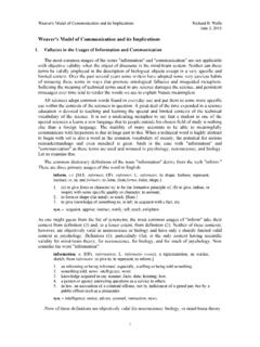
2 23 InputTransitionRiseor Fall Rateas Specifiedin Supply-CurrentChangeof the Inputat TTL Levelas Specifiedin (36 Inputs ).. (SN74 ACT107x)..711 UpperClampingDiodeCharacteristics(SN74 ACT107x)..812 LowerClampingDiodeCharacteristics(SN74 ACT107x)..813 InputStructureof ABT/LVTand OutputVoltage V InputVoltage V Low OutputWaveformsof DriverWithand to HighOutputWaveformsof DriverWithand - input Voltage - VICC - Supply Current - mA01234560246810121416D001 ABT DEVICESLVT/LVC DEVICESQnQpInputInverterVCCTo theInternal StageD1Q1 InputInverterDrops Supply VoltageTo theInternal StageQnQpVCCC haracteristicsof Slowor July 1994 RevisedSeptember2016 SubmitDocumentationFeedbackCopyright 1994 2016,TexasInstrumentsIncorporatedImplica tionsof Slowor FloatingCMOSI nputs20 PowerPlot of the InputPowerWithBus Holdat of the InputPowerWithoutBus Holdat Data-SheetMinimumSpecificationfor Bus a trademarkof othertrademarksare the propertyof Slowor FloatingCMOSI nputsBothCMOSand BiCMOS familieshavea structureis an inverterconsistingofa p-channelto VCCand an n-channelto GNDas shownin Figure1.
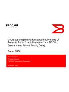
3 Withlow-levelinput,the P-channeltransistoris on and the N-channelis off, causingcurrentto flow fromVCCand pullingthe nodeto a ,the n-channeltransistoris on, the P-channelis off, and the currentflowstoGND,pullingthe nodelow. In bothcases,no currentflowsfromVCCto ,whenswitchingfromone stateto another,the inputcrossesthe thresholdregion,causingthe N-channeland the P-channelto turn on simultaneously,generatinga currentpathbetweenVCCand currentsurgecan be damaging,dependingon the lengthof time that the inputis in the thresholdregion( to 2 V).The supplycurrent(ICC) can rise to severalmilliamperesper input ,peakingat (seeFigure2). This is not a problemwhenswitchingstateswithinthe data-sheet-specifiedinputtransitiontimel imit specifiedin the recommendedoperatingconditionstablefor the InputStructuresof ABTand LVT/LVCD evicesVCC= 5 VTA= 25 COne Bit is DrivenFrom0 V to 6 VFigure2.
4 SupplyCurrentVersusInputVoltage(OneInput )VIVGNDLGNDIOVI` July 1994 RevisedSeptember2016 SubmitDocumentationFeedbackCopyright 1994 2016,TexasInstrumentsIncorporatedImplica tionsof Slowor FloatingCMOSI nputsRecommendedOperatingConditions(1)MI NMAXUNIT t/ vInputtransitionrise or fallrateABToctals5ns/VABTW idebus and Widebus+ 10 AHC,AHCT20FB10 LVT, LVC, ALVC, ALVT10LV100LV-AVCC= V to V200 VCC= 3 V to V100 VCC= V to V20ttInputtransition(riseand fall)timeHC, HCTVCC= 2 V1000nsVCC= V500 VCC= 6 V400(1)Referto the latestTI datasheetsfor InputTransitionRiseor Fall Rateas Specifiedin DataSheets2 SlowInputEdgeRateWithincreasedspeed,logi cdeviceshavebecomemoresensitiveto slowinputedgerate,coupledwith the noisegeneratedon the powerrails whenthe outputswitches,can causeexcessiveoutputerrorsor occurif an unusedinputis left floatingor isnot activelyheld at a due to voltagetransientsinducedon the device s powersystemas theoutputload current(IO) flowsthroughthe parasiticlead inductancesduringswitching(seeFigure4).
5 Becausethe device s internalpower-supplynodesare usedas voltagereferencesthroughouttheintegrated circuit,inductivevoltagespikes,VGND, affectthe way signalsappearto the example,as the voltageat the device s groundnoderises,the inputsignal,VI', appearstodecreasein undesirablephenomenoncan thenerroneouslychangethe outputif the caseof a slowlyrisinginputedge,if the changein voltageat GNDis largeenough,the apparentsignal,VI', at the deviceappearsto be drivenbackthroughthe thresholdand the outputstartsto switchinthe worst-caseconditionsprevail(simultaneous lyswitchingall of the outputswithlargetransientload currents),the slowinputedgeis repeatedlydrivenbackthroughthe threshold,causingthe outputto ,the maximuminputtransitiontime of the deviceshouldnot be violated,so no damageto the circuitor the input /OutputModelVI - input Voltage - VICC - Supply Current - July 1994 RevisedSeptember2016 SubmitDocumentationFeedbackCopyright 1994 2016,TexasInstrumentsIncorporatedImplica tionsof Slowor FloatingCMOSI nputsIf a V and 2 V is appliedto the inputfor a prolongedperiodof time,this situationbecomescriticaland shouldnot be ignored,especiallywith higherbit countand moredensepackages(SSOP,TSSOP).
6 For example,if an 18-bittransceiverhas 36 I/O pins floatingat the threshold,the currentfromVCCcan be as high as 150 mA to 200 mA. This is approximately1 W of powerconsumedby thedevice,whichleadsto a continuousoverheatingof the ,becausethe inputsare in the thresholdregion,the outputstendto oscillate,resultingindamageto the internalcircuitovera long periodof datasheetshowsthe increasein supplycurrent( ICC) whenthe inputis at a TTL level[for ABTVI= V, ICC= mA (seeFigure5)]. Thisbecomesmorecriticalwhenthe inputis in the thresholdregionas shownin typicalfor all cmos inputcircuits,includingmicroprocessorsan d CBTor CBTLV devices,this appliesto the FB and GTLdevices,this appliesto thecontrolinputsand the TTL (unlessotherwisenoted)(1)MINMAXUNIT ICC(2)ABT, AHCTVCC= V,One inputat V,Otherinputsat VCCor V,One inputat V,Otherinputsat VCCor ICC(2)CBTLVC ontrolinputsVCC= V,One inputat 3 V,Otherinputsat VCCor GND750 A ICC(2)LVCVCC= 3 V to 3 6 V,One inputat V,Otherinputsat VCCor , ALVC, (1)Referto the latestTI datasheetsfor devicespecifications.
7 (2)This is the increasein supplycurrentfor eachinputthat is at the specifiedTTL voltagelevelratherthanVCCor Examplesof Supply-CurrentChangeof the Inputat TTL Levelas Specifiedin DataSheetsVCC= 5 VTA= 25 CAll 36 Bits are DrivenFrom0 V to 6 VFigure6. SupplyCurrentVersusInputVoltage(36 Inputs )OZI50 AV V sC20 pFP' ' DesigningMore-ReliableSystems5 SCBA004D July 1994 RevisedSeptember2016 SubmitDocumentationFeedbackCopyright 1994 2016,TexasInstrumentsIncorporatedImplica tionsof Slowor FloatingCMOSI nputsAs long as the driveris activein a transmissionpathor bus, the receiver s inputis alwaysin a inputspecificationis violatedas long as the rise and fall timesare withinthe ,whenthe driveris in a high-impedancestate,the receiverinputis no longerat a definedleveland tendsto situationcan worsenwhenseveraltransceiverssharethe samebus. Figure7 isan exampleof a typicalbus transceiversare inactive,the bus-linelevelsare voltagethat is determinedby the leakagecurrentsof eachcomponenton the bus is reached,theconditionis knownas afloatingstate.
8 The resultis a considerableincreasein powerconsumptionand arisk of damagingall componentson the bus. Holdingthe inputsor I/O pins at a validlogiclevelwhentheyare not beingusedor whenthe part drivingthemis in the high-impedancestateis TypicalBidirectionalBus3 Recommendationsfor ControlThe simplestway to avoidfloatinginputsin a bus systemis to ensurethat the bus alwaysis eitheractiveor inactivefor a limitedtime whenthe voltagebuildupdoesnot exceedthe maximumVILspecification( for TTL-compatibleinput).At this voltage,the correspondingICCvalueis too low and the deviceoperateswithoutany problemor concern(seeFigure2 and Figure4).To avoiddamagingcomponents,the designermustknowthe maximumtime the bus can ,assumingthat the maximumleakagecurrentis IOZ= 50 mA and the total capacitance(I/O and linecapacitance)is C = 20 pF, the changein voltagewith respectto time on an inactiveline that be calculatedas shownin Equation1.
9 (1)The permissiblefloatingtime for the bus in this exampleshouldbe reducedto 320 ns maximum,whichensuresthat the bus doesnot exceedthe time constantdoesnot changewhenmultiplecomponentsare involvedbecausetheirleakagecurrentsand capacitancesare advantageof this methodis that it requiresno additionalcost for ,this methoddoesnot alwaysapplybecausebusesare not Pull-downResistorsWhenbusesare disabledfor morethanthe maximumallowabletime,otherwaysshouldbe usedtopreventcomponentsfrombeingdamagedo r pull-upor a pull-downresistorto VCCor GND,respectively,shouldbe usedto keepthe bus in a size of the resistorplaysan importantrole and,if its resistanceis not chosenproperly,a problemmay ,a 1-k to 10-k maximuminputtransitiontime mustnot be violatedwhenselectingpull-upor pull-downresistors(seeFigure3). Otherwise,componentsmay oscillate,or devicereliabilitymay be 15 pF 2 C N u u C u Tt RCCCCCiV(t) VeVV RRVCCBUSVCCV(t) July 1994 RevisedSeptember2016 SubmitDocumentationFeedbackCopyright 1994 2016,TexasInstrumentsIncorporatedImplica tionsof Slowor FloatingCMOSI nputsFigure8.
10 Inactive-BusModelWitha DefinedLevelAssumethat an active-lowbus goesto the high-impedancestateas modeledin Figure8. CTrepresentsthe deviceplus the bus-linecapacitanceand R is a pull-upresistorto VCC. The valueof the requiredresistorcan be calculatedas shownin V(t) = 2 V, minimumvoltageat time t Vi= V, initialvoltage VCC= 5 V CT= total capacitance R = pull-upresistor t = maximuminputrise time as specifiedin the datasheets(seeFigure3).(2)Solvingfor R, the equationbecomes:(3)For multipletransceiverson a bus:where C = individualcomponentand tracecapacitance N = numberof componentsconnectedto the bus(4)Assumingthat thereare two componentsconnectedto the bus, eachwith a capacitanceC = 15 pF,requiringa maximumrise time of 10 ns/Vand t = 15-nstotal rise time for the input (2 V), the maximumresistorsize can be calculatedby Equation5:(5)This pull-upresistormethodis recommendedfor ac-poweredsystems.