Transcription of Inclinometer Probes - GEOKON
1 Geotechnical Instrumentation6000, 6100 SeriesOperating PrincipleInclinometer Probes are designed for use with standard, grooved Inclinometer casing. Spring-loaded wheels on the probe engage the grooves in the casing thus maintaining the probe in a known orientation. Casing is grouted inside near-vertical boreholes (boreholes at other angles can be accommodated with some loss of resolution); cast inside concrete piles or slurry walls; or attached to steel use, the Inclinometer probe is connected to a cable and lowered to the bottom of the casing and then raised in increments equal to the wheel spacing. At each increment the probe is read by a readout connected to the upper end of the cable. The readout gives a measurement of the tilt of the casing to the vertical, at each depth increment.
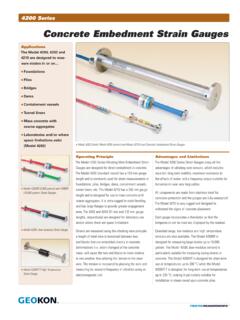
2 Repeat surveys of the casing reveal changes in these tilts, which can be analyzed to provide plots of lateral deflec-tions of the casing, in orthogonal directions, at every depth and LimitationsThe connector on the end of the probe is of extra-high quality (hermetically sealed, with gold plated pins) which helps improve signal accuracy. It s design is such that the connector can be easily removed and replaced if it suffers from damage or excessive wear. A protective cap is sup-plied to cover the cable connector when not in are self lubricated for longer life. In addition, the wheels are designed to be replaceable with minimal effort and expense, should wear become excessive. Model 6000/6100 Inclinometer Probe (probe appearance is essentially identical).
3 ApplicationsThe 6000 and 6100 series Portable Inclinometer Systems are used to determine and measure lateral movements in and Landslides Unstable Slopes Dam Embankments Landfills Slurry walls Caissons Piles Sheet Piling TunnelsInclinometer ProbesDISCONTINUEDThe Model 6000 Inclinometer Probe is designed to measure the tilt of vertical Inclinometer casing at selected depth increments, consists of a waterproof, stain-less steel housing, and contains two force-balanced accelerometers, one with its axis in the plane of the spring-loaded wheels, the other at 90 the base of the probe there is a rubber cushion designed to reduce shock load-ing on the accelerometer should the probe be dropped on to a solid surface.
4 The accelerometers are capable of withstanding a certain amount of rough handling (shocks < 1000 g) but allowing the probe to fall against hard surfaces can perma-nently damage the accelerometer requiring expensive factory repairs. Therefore, it is very important to handle the probe with care at all SpecificationsStandard Range1 53 Sensors 2 force-balanced accelerometersOutput @ 30 5 VDCR esolution2 mm/500 mm ( ft/2 ft) ( 10 arc seconds)Linearity 2 mm/30 mTotal System Accuracy3 6 mm/30 m ( in/100 ft)Temperature Range 0 C to +50 C (32 F to 122 F)Temperature Coefficient C ( F)Wheel Base m, 1 m or 2 ftLength Diameter4 700 25 mm, 1200 25 mm or 32 x 1 inCasing Size 51 to 89 mm (2 to in)Weight (with case) kg (16 lb)Shock Survival6 1000 g ( lb)
5 1 The calibrated range of the Inclinometer is 30 degrees from vertical, but the Inclinometer can be used at greater inclinations with a lessening in performance. 2 10 arc seconds. The resolution shown is only true in the range of 5 degrees from vertical. Beyond this, the resolu-tion is diminished (by the cosine of the angle from vertical). Resolution also depends on readout instrument used. 3 Within 3 of vertical. This takes into account the accumulation of the error inherent with each reading, and normal placement errors in positioning the probe inside the casing; also the effect of debris in the casing, or casing cable connector adds 150 mm to the length of the probe is designed for use in all standard Inclinometer casing up to a maximum diameter of 89 mm ( inches).
6 6 The Inclinometer Probe is a highly sensitive device and should be treated with great care at all times in order to maintain calibration. Particular attention should be given to preventing the probe from hitting the bottom of the casing with any Model 6100 MEMS Inclinometer Probe is identical to the Model 6000, except that it uses two MEMS (Micro Electro Mechanical Sensors) in place of the two force-balanced the base of the probe is a rubber cushion designed to reduce shock loading on the accelerometer, should the probe be dropped on to a solid surface. The accelerometers are capable of withstanding a certain amount of rough handling (shocks < 2000 g), but allowing the probe to fall against hard surfaces can perma-nently damage the accelerometer requiring factory repairs.
7 Therefore, it is very important to handle the probe with care at all 6100 MEMS Inclinometer Probe has a restricted range of 30 . This is more than ample for all nominally vertical boreholes. Custom-built 6100 MEMS Probes can be made to accommodate special applications, such as casings installed on the sloping face of a dam embankment.* Horizontal versions can also be supplied.*Special sensors for inclined slopes are not SpecificationsStandard Range 30 Sensors 2 MEMS sensorsOutput @ 30 4 VDCR esolution1 mm/500 mm ( ft/2 ft)Linearity 1 mm/30 mTotal System Accuracy2 3 mm/30 m ( in/100 ft)Temperature Range 0 C to +85 CTemperature Coefficient CWheel Base m, 1 m or 2 ftLength Diameter3 700 25 mm, 1200 25 mm or 32 1 inCasing Size 51 to 89 mm (2 to in)Weight (with case) kg (16 lb)Shock Survival5 2000 g 1 10 arc seconds.
8 The resolution shown is only true in the range of 5 degrees from vertical. Beyond this, the resolu-tion is diminished (by the cosine of the angle from vertical). Resolution also depends on readout instrument used. 2 Within 3 of vertical. This takes into account the accumulation of the error inherent with each reading, and normal placement errors in positioning the probe inside the casing; also the effect of debris in the casing, or casing cable connector adds 150 mm to the length of the probe is designed for use in all standard Inclinometer casing up to a maximum diameter of 89 mm ( inches).5 The Inclinometer Probe is a highly sensitive device and should be treated with great care at all times in order to maintain calibration.
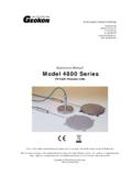
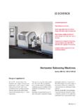
9 Particular attention should be given to preventing the probe from hitting the bottom of the casing with any impact. Model 6000 Inclinometer Probe. Model 6100 MEMS Inclinometer 6000 Inclinometer ProbeModel 6100 MEMS Inclinometer ProbeDISCONTINUEDThe World Leader in Vibrating Wire TechnologyTMGeokon maintains an ongoing policy of design review and reservesthe right to amend products and specifications without , Incorporated48 Spencer StreetLebanon, NH 03766 USA1 603 448 15621 603 448 2015 GEOKON , Incorporated. All Rights Reserved | Doc. Rev. , 01/15 Technical Specifications (FPC-1 Field PC)Operating Temperature 30 C to 60 CStorage Temperature 40 C to 70 CProcessor Marvell PXA310 806 MHzMemory 128 MB SDRAMData Storage 4 GB iNAND FlashOperating System Microsoft Windows Mobile 480 640 pixel Anti-glare " VGA resolution, touchscreen, sunlight readable 262K colors (18 bit), with LED backlightKeypad Numeric keypad with backlighting, on-screen QWERTY keyboardBattery 5600 mAh Li-ion battery packThe Model GK-604 Inclinometer Readout is a rugged, weather tight, easy-to-use, analog Inclinometer sys-tem capable of reading MEMS analog, Spiral Indicator and force balance type Inclinometer Probes .
10 In use, the MEMS analog and force balance type inclinometers are connected, by their control cables, to an interface, which may be stand alone (Model GK-604-4), or located inside the control cable reel (Model GK-604-3). The inter-face converts the probe signal and transmits the data via Bluetooth to the Model FPC-1 Field PC running the GK-604D IRA application. Readings are stored by tapping Record, or pressing the Enter button on the Field PC display. An audible beep indicates the completion of the reading storage. During Model GK-604 Inclinometer Readout Model FPC-1 Field PC showing an inclinom-eter data reading screen running of a deflection survey the Field PC has the capability of displaying the check sum on the LCD screen, a useful tool for checking the survey data in the field so that reading errors are surveys are complete, readings saved to the inter-nal SSD can be transferred to a host computer where data reduction, graphing and reporting can be accomplished using SiteMaster Software (sold separately please see the SiteMaster data sheet for further details).