Transcription of INCRA
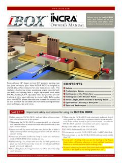
1 INCRAThe only table saw fence with patented Automatic Lead screw Positioning ControlTMSafety .. 2 Fasteners and Hardware Lists .. 2 Rail Assembly .. 4 Base Mount Assembly .. 6 Fence Assembly .. 8 Final Calibration .. 9 Blade Guard Adjustments .. 11 Extension Table .. 11 Auxiliary Fence Mounting .. 12 Maintenance .. 12 Warranty .. 12 CONTENTSP lease read this owner s manual and keep it at hand for : The INCRA TS-LS system consists of three packages. One of the packages contains the rails and another, the base mount unit. These two assemblies are covered fully by this owner s manual.
2 The third package contains the INCRA LS Positioner. Read all of this TS-LS owner s manual and the Safety, Getting Acquainted and Operations sections of the LS Positioner manual. If you have also pur-chased one of the router table extension wings, complete all assembly instructions in this manual BEFORE attaching the router just about an hour or so, you are going to be operating one of the most exciting new tools in today s woodshops. Your table saw will undergo a transfor-mation, and what was once an average saw will emerge a preci-sion woodworking machine, one you ll be proud of for years to come.
3 So take a few minutes to read over the safety information and mounting instructions, then grab a Phillips screwdriver and a set of wrenches and let s get started. OWNER S MANUAL6 each 3 8 16 x 11 2 hex bolt6 each 3 8 flat washer6 each 3 8 lock washer6 each 3/8 16 hex nut2 each 3 8 24 x 1 hex bolt (Delta Unisaw)4 each 5 16 18 x 11 2 hex bolt4 each 5 16 flat washer4 each 5 16 lock washer4 each 5 16 18 hex nut Before using the INCRA TS-LS, read and follow all of the instructions and safety information in this manual. When using the INCRA TS-LS in conjunction with any other tool, first read and follow all instructions and safety information in that tool s owner s manual.
4 Never let any part of the INCRA TS-LS interfere with another tool s safety guards or other safety equipment. Before using your INCRA TS-LS, make sure all mounting screws are tight and that the black clamping knobs are securely tightened to the rails. Always turn off the power and make sure that the blade is fully stationary before changing the setting on any part of the INCRA TS-LS. Always keep both hands behind the fence when moving the INCRA TS-LS to a new setting. Before making a cut, always make sure that the carriage clamp is fully engaged and that the rail hook thumbscrew is securely tightened.
5 Use appropriate safety devices. Keep hands clear of the saw blade! Always use a push stick, rubber soled push block, or other safety devices to keep your hands safely away from the saw blade. Never let the saw blade come into contact with any part of the INCRA TS-LS or LS Positioner. Wear safety glasses, hearing protection, and follow all normal shop safety practices. Never operate your table saw without a blade guard. SAFETY FASTENERS (ACTUAL SIZE) Mounting Bracket Hardware Pack B-01 Note: Extra hardware is provided in this pack to ensure compatibility with a wide variety of table saws.
6 Only four of the bolts will be used in a typical safety instructions for using the INCRA TS-LS 2 INCRA Woodworking Tools & Precision Rules 6 each3 8 16 x 3 4 hex bolt6 each1 4 20 square nut10 each3 8 16rectangular nut8 each#10 32 x 7 16 Phillips flat head screw8 each#10 32 hex nutRail Hardware Pack B-02 Base Mount and Fence Glide Hardware Pack B-0310 each3 8 flat washer6 each1 4 20 x 1 2 socket head cap screw6 each1 4 flat washer4 each3 8 16dual pilot rectangular nut4 each 3 8 16 x 3 4 clamping knob4 each3 8 16 x 1 2 hex bolt8 each#10 32 x 3 8 Phillips pan head screw8 each#10 flat washer8 each#10 32 hex nut4 each3 16 thick nylon washer4 each3 8 16 x 3 8 socket head set screwLS Mounting Hardware Pack B-04 INCRA TS-LS Owner s Manual 3 Note: Each hardware pack is labeled and bagged separately.
7 Open each pack as it is called for in the instructions to simplify INCRA Woodworking Tools & Precision Rules Unplug your table saw and remove the existing fence, including the front and rear support rails, mounting brackets, and the blade : The blade guard must be reinstalled after you have finished mounting the INCRA TS-LS to your table mounting bracketsAttach (4) mounting brackets to the cast iron surface of your table saw using the supplied hardware. See Fig. 1. The Mounting Bracket Hardware Pack B-01 contains a variety of fasteners which will work with most table saws.
8 Use the largest bolts in the pack that will fit your saw s existing mounting holes. If the holes in your table saw are threaded, use the fastener arrangement shown in Detail 1A. If the mounting holes are not threaded, use the fastener arrangement shown in Detail 1B. Position the mounting brackets 1 4 below the table top as shown in Details 1A and 1B and snug the fasteners to hold the brackets in place. DO NOT TIGHTEN THE BOLTS AT THIS TIME. (Discard any remaining fasteners from the Mounting Bracket Hardware Pack B-01.)Loosely attach rail boltsOpen the Rail Hardware Pack B-02.
9 Add a 3 8 flat washer to each of (4) 3 8 16 x 3 4 hex bolts. Place the bolts through the holes in the mounting brackets and loosely attach the 3 8 16 rectangular nuts . See Fig. 2 rails onto mounting brackets and tighten boltsCarefully slide the rails onto the mounting brackets so that the rectangular nuts are captured in the T-slot on the bottom of the rail. Fig. 3 shows the correct orientation for the front and back rails. Approximately center the length of the rails on your table saw and tighten the mounting bolts that secure the rails to the 1 Attach rail mounting bracketsUse appropriate mounting hardware from the Mounting Bracket Hardware Pack B-01 to attach brackets (See Details 1A and 1B)Rail mounting bracketsThreaded holes in table sawLock washerThrough holes in table saw (Not threaded)Flat washerLock washerWeb RAIL ASSEMBLYDETAIL 1 ADETAIL 1 BFIG.
10 2 Loosely attach rail bolts23 Orient rails so that web is vertical and off center T-slot faces the saw as shown belowRear railOff center T-slot faces table sawWebFIG. 3 Front and rear rail orientation1 4 Table saw topTable saw top3 8 16 rectangular nutMounting bracket3 8 16 x 3 4 hex bolt3 8 flat washer1 4 Table sawFlat washerHex nutFront rail1 The rail positions described above will provide support for the base of the TS-LS for work on either the left or right side of the blade. Left hand range is about 16 and right hand range is 32 or 52 depending on your rail length.