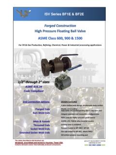
Transcription of INDEX Flow Rates for Ball Valves
1 Click on Produce Code / Description to Be Linked to That Page Valves /COUPLINGS. Safe Practice Requirements for Ball Valves F3. SLV / SSV Lockable Ball Valves F4. CLBV Clipline Ball Valve F7. SPBV Threaded BSPP Ball Valve F8. Ball Valve Accessories Handles Seal Kits Lock Plate F 10. Large Bore / Flanged / Stainless Steel Ball Valves F 12. SSBV Stainless Steel High Pressure Ball Valves F 13. INDEX . STBV 3-Way Ball Valves F 15. Flow Rates for Ball Valves F 16. Couplings Pictorial INDEX F 17. ISO-A and ISO-B Couplers F 18-23. 7000 / 7500 Series Flat Face Couplers F 24. 7200 / 7600 Series Couple under Pressure Flat F 25. Face 8000 Series Screw to Connect Couplers F 26-27.
2 9000 Series Tema' Compatible High Flow Couplers F 28. 9500 Series High Flow Couplers F 29. DQ Series Diagnostic Couplers F 30. 3000 Series Enerpac' Compatible Couplers F 31. 2000 Series Inline Check Valves F 31. SJ Series Swivel Joints F 32. This page is part of a complete catalogue containing technical and safety data. 1. All data must be reviewed when selecting a product. Pirtek reserve the right to change technical specifications without notice Rev. P F. BALL Valves . NOTES. BALL Valves . 2 This page is part of a complete catalogue containing technical and safety data. All data must be reviewed when selecting a product. F Pirtek reserve the right to change technical specifications without notice HIGH PRESSURE BALL Valves .
3 BALL Valves . SAFE PRACTICE REQUIREMENTS. GENERAL INSTRUCTION Use only clean undamaged seals of the correct Standard Ball Valves must be operated only at the positions of the stop between flanges pins ie fully open or fully closed Use correct size and strength of bolts, and heed length of Never use a ball valve to control or throttle flow - seals and seats engagement requirements in tapped holes will be damaged and heat will be induced to the system Heed good welding practice when using welded end Valves Do not use mechanical aids to assist turning ball Valves (gripping Eliminate any welding residue to ensure a clean internal space jaws on spindles, levers, pipe extensions, hammers etc)
4 Of the valve Ensure all special operating conditions concerning the Ensure the ball cavity remains within tolerable limits during the application are communicated to the supplier before selecting welding process to prevent distortion and seat / seal damage a ball valve (including criteria such as humidity, vibrations, Ensure the installed valve meets with the requirements of the operation frequency, electromagnetic fields, explosive zones, pipe layout to ensure proper accessibility anti-static etc) INITIAL OPERATION. Store Valves as supplied in a dry area free of contamination and Reread all instructions and operational requirements prior to with protective caps in place commissioning, and gain any necessary approvals BALL Valves .
5 Do not operate ball Valves more than 10 times per minute in Use only qualified personnel for initial commissioning of the explosive zones, as induced heat may create a dangerous system situation Note that the operating torque of a valve that has been in Always wear storage or has been in the same operating position for a protective gloves - the prolonged period will be noticeably higher than published handle will adopt the breakaway torques temperature of the Fully bleed the pipeline system before initial operation fluid ALL AIR BUBBLES MUST BE REMOVED PRIOR TO FULL. Never modify a PRESSURISATION. RISK OF EXPLOSION!! ball valve by drilling mounting holes, Build the pressure up slowly welding etc If a ball valve is used as a pipe line termination point, the open end adaptor must be properly closed to prevent any internal debris being expelled unexpectedly INSTALLATION.
6 MAINTENANCE & SURVEYS. Use only a ball valve that is correctly matched to the intended application with regard to pressure rating, materials of When draining a system to prevent frost damage or for cleaning, construction, operating temperature, port configuration and lock drain the ball cavity by opening the ball to the 45 position out capabilities Disassembly of ball Valves must only be performed by authorised EN ISO stipulates that a ball Valves must turn 1/4 turn Personnel only clockwise to close the valve, and incorporate a notch on the Poor quality sealants must not be used for storage spindle to show the current ball position Inspect Valves regularly for proper operating function (6 monthly Installation should be by qualified people and in a totally minimum).
7 Depressurised pipe system Replace corroded, leaking or immovable ball Valves without Clean thoroughly all system components prior to installation to delay prevent damage to the sealing elements REMOVAL FROM SERVICE. Always hold any end Never remove a ball adaptors securely valve without first to counter torque relieving system loads when tightening pressure fittings Always turn a valve Do not tighten or to the mid position to loosen the end properly relieve the adaptors from their internal cavity pressure factory settings in any Drain the system of fluid way completely Always drain a valve and the complete system before Wear personal protective dismantling if dealing with toxic, combustible or explosive media equipment as necessary With flanged Valves , ensure flange connection bolts are properly FLOW Rates .
8 Centred with the opposing flange before tightening bolts in a See page F 16. crosswise procedure This page is part of a complete catalogue containing technical and safety data. 3. All data must be reviewed when selecting a product. Pirtek reserve the right to change technical specifications without notice F. SLV / SSV. BALL Valves . LOCKABLE BALL Valves . STANDARD AND SUPER STAPLE. Spindle removal is impossible when a 38mm dia scissor lock is in place, allowing tamper-proof operation Male - Female or Female - Female BALL Valves . configurations Description: Materials and Specifications: Features: Steel bodied ball valve with either fixed Passivated zinc corrosion protection Handles can be colour coded to customer female or male - female configurations All steel construction request (red is standard).
9 Patented safety locking design that is fully Nitrile seals Mounting holes are incorporated in some compliant with padlock and scissor lock in styles - Refer Pirtek High working pressures common use, refer to note. NOTE: 38mm dia. Safety lockout Handle movement involves a lift and Able to be configured to the customer jaws and / or 6mm dia. shackle safety twist operation, preventing tampering or requirement as to handle position (standard padlock to be used only. disassembly when a padlock is in place (the configuration is for the valve to be closed lifting action is prevented by the presence when the handle is in the pictured position). of a padlock). Temp. Range -20 to +100 C with standard seals Spindle nut tool Lock spigot PROCEDURE TO ALTER THE LOCK FUNCTION.
10 Spring 1. Start with the handle in the open position 2. Unscrew the spindle nut at the top of the handle (use the tool circled at left). 3. Remove the lock spigot and spring before sliding Handle the handle vertically clear of the operating spindle 4. Rotate the handle through 1/2 turn anti-clockwise 5. Refit the handle in the new position Operating 6. Replace the spring and lock spigot spindle 7. Secure the handle using the spindle nut tool REPLACEMENT HANDLE REPAIR KIT. The components shown at left (excluding the valve body and spindle nut tool) can be ordered using Product Code SV-HD6RD-KIT. SPINDLE NUT TOOL. Available to order using Product Code SLV-TOOL. 4 This page is part of a complete catalogue containing technical and safety data.