Transcription of Inductance Measurement Using an LCR Meter and a …
1 Inductance Measurement Using an LCR Meter and a Current Transformer Interface Bryan Waltrip1, Svetlana Avramov-Zamurovic2, Andrew Koffman1 1 National Institute of standards and Technology*, Gaithersburg, Maryland, USA 2 United States Naval Academy, Annapolis, Maryland, USA Keywords: Inductance , LCR Meter , current transformer, capacitance bridge, impedance Introduction Traditional calibration support for commercially available four-terminal-pair (4TP) LCR meters involves the use of capacitance, resistance , and Inductance standards with known frequency characteristics. This paper describes a new Inductance Measurement system where an unknown Inductance standard is compared to known capacitance and resistance standards Using a commercially available LCR Meter , a commercially available audio frequency capacitance bridge, and a multi-stage, programmable-ratio, current transformer. The described Measurement system is relatively simple, uses mainly commercially available instrumentation, and achieves acceptable Inductance Measurement uncertainty over the 50 Hz to 20 kHz frequency range.
2 It has been established that commercially available LCR meters have relatively good linearity characteristics over narrow Measurement ranges [1], making them well suited as transfer devices when comparing impedances of nominally equal values. In recent years, highly accurate, three-terminal (3T) capacitance bridges operating over the 50 Hz to 20 kHz frequency range have become commercially available with Measurement uncertainties approaching metrological levels [2]. In addition, multi-stage, amplifier-aided current transformers have been routinely developed that achieve errors below a few parts in 106 over the 50 Hz to 20 kHz frequency range [3-4]. In order to improve and simplify the present Inductance Measurement services at NIST, an attempt has been made to exploit these three technologies by developing a system to compare an Inductance standard under test to a capacitance standard having an equivalent impedance magnitude at the frequency of interest.
3 The GR1482 Inductance standards traditionally used for the dissemination of the Henry typically have large series resistance components, so equivalent impedances must be synthesized Using parallel combinations of capacitance and resistance standards . * Electronics and Electrical Engineering Laboratory, Technology Administration, Department of Commerce. Contribution of the Government. Not subject to copyright in the Proposed Approach In the proposed Measurement procedure, we first make an initial, low-accuracy Measurement of the Inductance standard under test Using an LCR Meter . From this Measurement , suitable resistance and capacitance standards are selected that will, when connected in parallel, result in an equivalent impedance magnitude. Since capacitors and inductors exhibit current flow with opposite phase, a current transformer interface is used to introduce a 180 phase shift in the capacitive current.
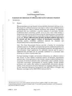
4 The current transformer based phase shift network, a programmable capacitor, and a programmable resistor are used in order to match the measured Inductance under test. The capacitance and resistance values are adjusted until the same LCR reading is achieved, within the resolution constraints of the programmable capacitor and resistor. Once the impedance is matched, the resulting capacitance, C, is measured Using a commercially available capacitance bridge and the resulting resistance , RP, is measured Using a LCR Meter (to determine its time constant) and also with a high-accuracy commercial DMM (to determine its dc resistance value ). The measured parameters are then used to calculate the impedance of the Inductance under test. The test procedure is outlined graphically in Figure 1. SLRLjZ+= LCR Meter LCR Meter Interface (phase shifter) Interface (phase shifter) C Scaling Factor RP Scaling Factor ZL Scaling Factor Inductor Programmable Capacitor, C Programmable Resistor, RP Step 1.
5 Measuring Inductor Step 2. Tuning Matching Impedances LCR Meter ( ) DMM (RDC) Capacitance Bridge Matching resistor, RP Matching capacitor, C Step 3. Measuring Matching Impedances Figure 1. Inductance Measurement Procedure The inductor is modeled Using a series resistance : LjRZSL +=. The capacitance and resistance matching network is modeled as a parallel network: PCRPRCjRZ +=1. Assuming that the impedance of the inductor, , is given (by the initial LCR Measurement ), and that the goal is to find the equivalent capacitance that has exactly the same magnitude but with a phase shift that is exactly 180 away from the phase shift of the inductor, then the equation for the phase relationship is: LZCRRLPS =, or PSRRLC= , (1) and the equation for the magnitude relationship is: 222)(1)()(CRRLRPPS +=+, or SSPRLRR2)( +=. (2) Once all the measurements are completed, the impedance of the inductor is given by: RCRCLLZZZZ''=, (3) where the impedances with primes are those measured with the LCR Meter and PPRCCRjRZ +=1 is calculated from the individually measured and values ( Using the capacitance bridge, DMM, and LCR Meter ).
6 Finally, the and values are given by: PRSRPCL{} LZLIm=, and . (4,5) {LSZRRe=} Present Inductance calibration services at NIST support Inductance values of L = [50 H, 100 H, 200 H, 500 H, 1 mH, 2 mH, 5 mH, 10 mH, 20 mH, 50 mH, 100 mH, 200 mH, 500 mH, 1 H, 2 H, 5 H, 10 H]. Supported frequencies are 100 Hz, 400 Hz, and 1 kHz for all standards , and 10 kHz for inductors up to 100 mH. This relatively large test space would normally require adjustable resistance and capacitance standards spanning many decades of possible values. To avoid unnecessary complexity, the current transformer is wound with three primary-secondary ratios, 1:100, 10:100 and 100:100, thereby adding an additional two orders of magnitude to the matching computations. A switching network is used to apply the optimal ratio when measuring different inductors and also to control the auto calibration process.
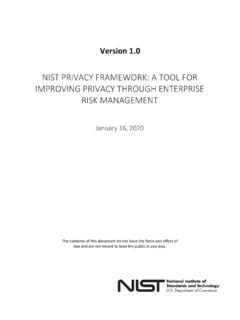
7 In order to achieve an optimal selection of resistors and capacitors satisfying the given design constraints, the apparent Inductance seen by the LCR Meter may be scaled up by a factor of 10 or 100 Using appropriate windings on the current transformer. Software routines were developed to select the matching components for the given set of inductors. Requivalent and Lequivalent are calculated Using rounded values for C and Rp according to their respective adjustment resolutions. In Table I, the results are presented for the set of standard inductors at a frequency of 10 kHz, where the nominal value , L, of the inductor is used and its measured serial resistance , RS, is given. The relative errors are given and only the values below 500 H indicate any appreciable differences between the RS and L values and the and LEQSREQ values that were calculated Using the finite resolution RP and C. This is not a problem, however, since it has been demonstrated that LCR meters of the type used in this system have linearity approaching parts in 106 over very wide (+ ) operating point margins [1].
8 L Rs ZL SF Rp R SF C C SF SSSRRREQ LLLEQ [H] [ ] [ ] [ F] [10-6] [10-6] 50e-6 100 75 1 1 100e-6 100 405 1 1 200e-6 100 1068 1 1 500e-6 100 1679 1 1e-3 100 3731 1 2e-3 10 701 10 1 54 5e-3 100 21825 1 10e-3 10 5027 10 20e-3 100 86316 1
9 50e-3 45 100 223825 1 100e-3 100 44861 1 200e-3 114 10 13966 10 5 500e-3 335 10 297965 10 1 616 10 64704 10 2 1350 1 118323 1 5 3600 1 277756 1 2 10 8450 1 475650 1 0 Table I. Obtained matching parameters for the set of inductors at 10 kHz. Results Simulations were performed to analyze type B uncertainties associated with the various system components.
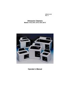
10 A plot of the Inductance Measurement uncertainties over the test space of interest (50 Hz to 20 kHz, 100 H to 10 H) is shown in Figure 2. 10-410-310-210-110010101020304050(each curve is a separate frequency). nominal Inductance (Henrys) Measurement Error (parts in 106) Figure 2. Type B Analysis of Inductance Measurement System. The analysis includes basic accuracy specifications for all system components including the LCR Meter basic accuracy and linearity, capacitance bridge performance specifications, DMM 4-wire Ohms specifications, and current transformer performance. The errors should represent a worst case analysis, since conservative bounds were used for many of the parameters. The most significant source of error occurs at low frequencies and at low Inductance settings. It is attributed to the uncertainty of the capacitance bridge estimate of the capacitor s dissipation factor. Errors in this estimate show up mathematically as the addition of a parallel resistance across RP, thereby affecting the ZRC estimate directly.