Transcription of Inductive Sensors - altechcorp.com
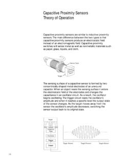
1 Switch end positionThreshold value switchOscillatorCoilObjectElectro-magnet icfieldInductive SensorsFunctional principleIn general , Inductive proximity switches consist of four basic elements: a coil, an oscillator, a threshold switch and an output stage with short-circuit protection. The oscillator generates a high frequency, electromagnetic alternating field which is emitted from the active face of the coil. Eddy currents are induced in a metal object that enters this field. These eddy currents draw energy from both the electromagnetic field and from the oscillator which is consequently attenuated. The more energy taken the closer the metal object moves towards the active face. The threshold switch switches on the output stage at a defined attenuation value. In proximity switches with a DC voltage supply, this switch is designed as an NPN transistor which switches the connected load to the negative pole or as a PNP transistor which switches the load to the positive pole.
2 The output stage is a thyristor or a triac in AC voltage switches. Sensing distanceThe sensing distance (gap) is determined by the coil diameter, larger Sensors are required for larger sensing distances. The sensing distance is also dependent on the size of the metal object to be detected as well as the material it is made from. TargetThe sensing distance is measured with a 1 mm thick square measuring plate made of steel (ST 37) referred to as a target. The edge length is equal to the diameter of the active face or equal to three times the sensing distance depending on which value is greater. Nominal sensing distance: (Sn)The nominal sensing distance is a device-specific characteristic value that is dependent on the coil sensing distance: (Sr)The real sensing distance is measured at nominal voltage and nominal temperature.
3 It must be between 90 % 110 % of the nominal sensing sensing distance: (Su)The useable sensing distance is measured within the permissible temperature and voltage ranges and is 90 % 110 % of the real sensing sensing distance: (Sa)(Assured operation distance)The operational sensing distance takes into account the influence of the supply voltage, temperature and control systems. Reliable switching under all permissible operating conditions is assured within 0 % 81 % of the nominal sensing distance. Sa ~ : (H)Hysteresis refers to the difference between the switch-on point as an object approaches and the switch-off point as the object moves away. This hysteresis is specified as a percentage of the nominal sensing distance and is typically 10 %. It is required to prevent the output chattering in response to slowly approaching objects, temperature drift, electrical interference or is the ability of a sensor to repeatedly detect and object at the same distance away from the sensing surface.
4 The typical deviation is < 5 %.Reduction factorsThe definition of the sensing distance is based on the measurement performed with a standardised square target made of steel. If other materials with the same dimensions are used, the sensing distance will be reduced as shown in the following torque examples for Sensors in brass NmM88 NmM1210 NmM1825 NmM3070 NmSwitching frequencyThe switching frequency is measured with a redating, non-conductive plate, on which the standard targets are mounted as illustrated (size of targets as previously defined).The distance between the targets and sensor is equal to half the nominal sensing distance. The maximum switching frequency is reached when the switch-on or switch- off signal time drops below 50 rangeFor most Sensors , the permissible ambient temperature range is between 25 C and +70 C ( 13 F to +158 F).
5 Sensors with an extended temperature range of 40 C to +100 C are also Sensors contain a coil on a ferromagnetic core that bundles the electromagnetic alternating field. The core is installed into the enclosure in such a way that the field emerges from the switch at the active face. A part of the magnetic field, however, also emerges from the side of the core. The sensor in a flush mount arrangement would already be influenced by the metal on the sides. For this reason, a metal band is fitted about the core in plastic enclosures, thus restricting the lateral magnetic field in a flush mount configuration. Due to the pre-attenuation attributed to the metal ring or a metal enclosure, flush mount versions have a shorter sensing distance than non-flush mount Sensors and can be mounted closer to each mountCatalogue symbol for flush mountThe active face can be flush with a metal mountCatalogue symbol for non-flush mountSensors for non-flush mount require a clearance equal to three times the sensor enclosure diameter and a min.
6 Depth of 2x spacing between non-flush mount sensorsInstallation with a mounting bracket parallel to a steel wallNAMUR Sensors (Standardization association for measurement and control in chemical industries)Protection classCorresponding to their ID code, the enclosures are dustproof and waterproof in accordance with IP 65 or IP 67 (EN 60529).Short-circuit protectionStandard Sensors are predected against short-circuit (cyclic) and polarity torque requirementsBERNSTEIN supplies corresponding mounting nuts with its Sensors . Refer to the respective datasheets for the required tightening Sensors are predected by a glass fibre reinforced thermoplastic, brass or stainless steel enclosure. The connection cable has a PVC or PU systemsThe following connection systems are available for standard Sensors : Cable variants (2 m) with PVC or PUR sheathing Connector variants with M8, M12 connector or connector conforming to DIN 43650 Quick-connect system with Ultralock connectorsStandards and approvalsAll Sensors are CE-certified.
7 The following European standards apply in accordance with CENELEC: EN 60947-5-2 proximity switches EN 60947-5-6 NAMUR sensors7


![CHART IV Height [m] Tightening torque for cable …](/cache/preview/6/a/f/4/7/b/b/c/thumb-6af47bbcb6409fcc2e4905d446934219.jpg)