Transcription of INDUSTRIAL INSTRUMENTATION - idc-online.com
1 IntroductionIndustrial flow measurements include measuring of flow rate of solids, liquids and gases. Thereare two basic ways of measuring flow ; one on volumetric basis and the other on weight materials are measured in terms of either weight per unit time or mass per unit rarely solid quantity is measured in terms of volume. Liquids are measured either involume rate or in weight rate. Gases are normally measured in volume rate. In this chapter,the flow measurements of liquids and gases will be discussed in detail rather than that are classified into two types, namely incompressible and compressible. Fluids inliquid phase are incompressible whereas fluids in gaseous phase are compressible. Liquid oc-cupies the same volume at different pressures where as gases occupy different volumes atdifferent pressures.
2 This point has to be taken care of while calibrating the flow meters. Themeasurements taken at actual conditions should be converted either to Standard temperature(0 C) and pressure (760 mm Hg) base (STP base) or to Normal temperature (20 C) and pres-sure (760 mm Hg) base (NTP base). Units of FlowThe units used to describe the flow measured can be of several types depending on how thespecific process needs the Normally expressed in weight rate like Tonnes/hour, Kg/minute Expressed both in weight rate and in volume : Tonnes/hour, Kg/minute, litres/hour, litres/minute, m3/hour Expressed in volume rate at NTP or STP like Std m3/hour, Nm3/hour Expressed in weight rate like Tonnes/hour, Kg/minutes etc. Steam density atdifferent temperatures and pressures vary.
3 Hence the measurement is converted into weightrate of water which is used to produce steam at the point of Measurement of FlowFlow meter is a device that measures the rate of flow or quantity of a moving fluid in an openor closed conduit. Flow measuring devices are generally classified into four \N-IND\CH-5-12 INDUSTRIAL INSTRUMENTATIONC-8\N-IND\BOOK1-1 They are :1. Mechanical type flow meters. Fixed restriction variable head type flow metersusing different sensors like orifice plate, venturi tube, flow nozzle, pitot tube, dall tube, quan-tity meters like positive displacement meters, mass flow meters etc. fall under mechanicaltype flow Inferential type flow meters. Variable area flow meters (Rotameters), turbineflow meter, target flow meters Electrical type flow meters.
4 Electromagnetic flow meter, Ultrasonic flow meter,Laser doppler Anemometers etc. fall under electrical type flow Other flow meters. Purge flow regulators, Flow meters for Solids flow measure-ment, Cross-correlation flow meter, Vortex shedding flow meters, flow switches working principle construction, calibration etc. of the above flow meters will bediscussed in the following Mechanical FlowmetersFixed restriction variable head type flow meters using different sensors like orifice plate, venturitube, flow nozzle, pitot tube, dall tube, quantity meters like positive displacement meters,mass flow meters are the popular types of mechanical flow of Fixed Restriction Variable Head Type FlowmetersIn the variable head type flow meters, a restriction of known dimensions is generallyintroduced into pipeline, consequently there occurs a head loss or pressure drop at the restric-tion with increase in the flow velocity.
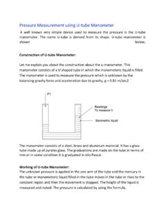
5 Measurement of this pressure drop is an indication ofthe flow lineFig. representation of a one dimensional flow system with a restrictionFLOW3C-8\N-IND\BOOK1-1 Head type flow measurement derives from Bernoulli s theorem which states that in aflowing stream, the sum of the pressure head, the velocity head and the elevation head at onepoint is equal to their sum at another point in the direction of flow plus the loss due to frictionbetween the two points. Velocity head is defined as the vertical distance through which aliquid would fall to attain a given velocity. Pressure head is the vertical distance which acolumn of the flowing liquid would rise in an open-ended tube as a result of the static general, a one dimensional flow system is assumed.
6 The schematic representationof such a system with a restriction in the pipeline is shown in Fig. Flow of Incompressible Fluids in PipesSection-1 is the position of upstream tap and Section-2 that for downstream. The termsT, A, , V, P and Z represent Temperature, Area, Density, Stream velocity, Pressure and Centralline elevation respectively. If this elevation is quite small such that Z2 Z1 is negligible, theBernoulli s equation for an incompressible ( 1 = 2) frictionless and adaptive flow is written as PV PV12122222 +=+ ( )whereg = acceleration due to gravity, giving P1 P2 = V222 g [1 (V1/V2)2]..( )The continuity equation for this type of flow is Q = A2V2 = ( )where Q = volume flow rate in m3 equations ( ) and ( ) and manipulating, one getsQ = A2V2 = AAAPAM2221212122[(/)](P) LNMMOQPP=gghva.
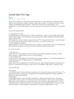
7 ( )where Mva = 112 AA21 FHGIKJ = Velocity approach factor h=P P12 = Differential is equation for the ideal volume flow actual flow conditions with frictional losses present, a correction to this formula isnecessary. Besides, the minimum area of flow channel occurs not at the restriction but at somepoint slightly downstream, known as the Venacontracta . This in turn depends on the flowrate. While the tapping positions are fixed, the position of maximum velocity changes withchanging flow basic equations are :V = K1 ( )Q = K1A ( )W = K1A ( )4 INDUSTRIAL INSTRUMENTATIONC-8\N-IND\BOOK1-1whereV = Velocity of FluidQ = Volume flow rateW = Mass flow = Cross-sectional area of the = differential head between points of measurement. = density of the flowing fluidK1 = Constant which includes ratio of cross-sectional area of pipe to cross-sectional area of nozzle or other RatioMost variable head meters depend on a restriction in the flow path to produce a changein velocity.
8 For the usual circular pipe, the Beta ratio is the ratio between the diameter of therestriction and the inside diameter of the pipe. = ( )whered = diameter of the restrictionD = inside diameter of the Reynolds NumberIn practice, flow velocity at any cross section approaches zero in the boundary layeradjacent to the pipe wall and varies across the diameter. This flow velocity profile has a signifi-cant effect on the relationship between flow velocity and pressure difference developed in thehead Osborne Reynolds proposed single, dimensionless ratio known as Reynolds number,as a criterion to describe this phenomenon. This number, Re, is expressed asRe = ( )whereV = velocityD = Diameter of the pipeline = density and = absolute number expresses the ratio of inertial forces to viscous forces.
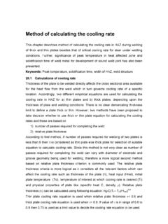
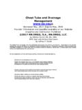
9 At a very lowReynolds number, viscous forces predominate and inertial forces have little effect. At highReynolds number, inertial forces predominate and viscous effects become Discharge Coefficient (Cd)Discharge coefficient, C is defined as the ratio between actual volumetric flow rate andideal volumetric flow rate. Cd = ( )whereqactual = Actual volumetric flow rate qideal = Ideal volumetric flow rate. (Theoretical)FLOW5C-8\N-IND\ Flow Coefficient (K)K = Cd/14 ..( )whereK = Flow coefficient Cd = discharge coefficient = ratio of diameters = d/Dwhere 1/14 is known as velocity approach factor (that is velocity at section-A1) Mva. K = Cd . MvaFig. and Pressure-Differential MeasurementMeasuring fluid flow with an orifice and differential pressure manometer as shown inFig.
10 , requires that the effect of the fluid over the manometer liquid be taken into , the pressure differential at the orifice is usually expressed in liquid-columnheight. ThenP1 P2 = ( m f) ( )whereh = differential at restriction, liquid column height m = weight density of manometer fluid f = weight density of fluid over the manometer if the flow rate is to be converted at the control room temperature at which thefluid density is s, then from equations ( ), ( ) and ( ).Q = KA2 2ghmfs(). = KA2 2ghmfs () ..( )6 INDUSTRIAL INSTRUMENTATIONC-8\N-IND\ Flow of Compressible Fluids in PipesIf the fluid is compressible, a flow rate can be obtained if the gas is considered ideal andthe flow is considered relation between pressure and velocity for flow of a compressible fluid through anorifice can be found from the law of conservation of energy as employed in no heat flow to or from the fluid and no external work done on or by the fluid andneglecting the very small datum level difference (Z1 Z2), we have P2v2 + V222g + JE2 = P1v1 + V122g + ( )whereE = internal molecular energy of fluidJ = work equivalent of heatv = Specific volume of fluidEmploying the definition of enthalpy H gives V22 V12 = 2gJ (H1 H2).