Transcription of Influence of External Currents in Sensors Based on …
1 Influence of External Currents in Sensors Based on PCB. Rogowski coils Artero , Arcega 2, 1. Endesa Distribuci n C/ San Miguel 1, 50001 Zaragoza 2. Department of Electrical Engineering Escuela Universitaria de Ingenier a T cnica Industrial de Zaragoza (E U I T I Z.), University of Zaragoza Rio Ebro Campus Mar a de Luna, n 3 Ed. Torres Quevedo , 50018 Zaragoza (Spain). phone:+34 976 762169, fax:+34 976 762226, e-mail: Abstract. A current sensor Based in the Rogowski coil is an electrical connection in the appropriate way, the External innovative measuring system that gives advantages with respect magnetic fields cancel in the system of the two coils . to conventional measuring systems Based in current More closer the coils are and more symmetrical his position, transformers with magnetic core [1], [2].and [3]. Their main better is the measurement and lower the error produced by advantages are: the linearity, the span and the bandwidth.
2 External Currents or magnetic fields. Different kinds of manufacturing allow to obtain an important variety of Rogowski coils with different properties. One way of 2. Rogowski coil construction manufacturing is using the same method as for producing There are two main ways to manufacture a Rogowski coil. The printed circuit boards, so by this way is possible to produce classical one consisting in wrapping in a flexible core (non coils very similar and with a high precision. magnetic) the cable of the coil. The second one more The authors are working in current measurement with innovative, consists in wrapping in a hard core the turns of Rogowski coils or Hall effect Sensors and in particular in the the cable. In that case is better to use the techniques of the realization of good and accurate coils [4] and [5]. In this work, printed circuit board manufacturing, using the two sides of the the Influence of External Currents to the coil in the measured board.
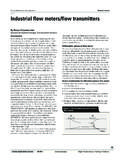
3 Each side of the board has part of the circuit of the turn. current by the coil has been evaluated. The junction of the two sides is through the board and by means of a welding. Industrial techniques are better than research ones Key words: Rogowski coils , current measurement, Sensors and in the production process smaller coils can be produced than in the research process. 1. Introduction The final result is an helicoidal coil, shown in figure 1, similar to a conventional Rogowski coil but the width is determined by One interesting alternative to the classical Rogowski coils the width of the PCB and a very well known geometry that is manufactured with conductor cable is to manufacture the coil very easy to simulate in order to study the electromagnetic like a printed circuit board (PCB) [6], [7] and [8]. The main problem.
4 Advantages of this coil are : a) Easy to manufacture b) Very cheap y light c) Good linearity and bandwidth The main inconvenience is that the step of each turn is relatively high with respect to a conventional coil, because the number of turns in a PCB coil is lower than in a conventional coil. This is the weakest point of this kind of coils because the errors produced by External Currents (or External varying magnetic fields) in the vicinity of the coil can more easily introduce an error in the measurement. We have tested different configurations in the shape of the turns of the coil for minimizing the error. An acceptable result has been obtained placing two coils in parallel position and very closer together, whose turns are in opposite direction. With an Fig. 1. PCB Rogowski coil plus integrator circuit 1. 277 RE&PQJ, Vol.
5 1, , March 2005. by the current will be created through the surfaces indicated by The working principle of this PCB coils is the same as for the sections II and III in the figure 2. flexible coils and has been explained in the literature [1]. The current to be measured (varying with the time) gives rise z to a magnetic flux changing with the time that is Ri translated to a voltage in the terminals of the Rogowski coil, proportional to the rate of current change Re di ( ). dt y The main characteristics of this kind of coils in comparison with conventional ones are: x Secci n I. A great accuracy. The way to manufacture the coil allow s to have a coil with dimensions and shape of the turns very Secci n II. constant in all the coil. A lower value of auto-inductance L for the same value of the mutual inductance M in comparison with a flexible Secci n III.
6 Coil. So the response of the coil and the bandwidth are improved. Fig. 2. Detail of a PCB Rogowski coil. Easy manufacturing and low cost. These coils are very interesting for several applications as for instance in We have built and simulated a series of prototypes of PCB. protection of power electric systems where they are Rogowski coils with 100 turns. The width is , the substituting the conventional current transformers with External radius is and the internal radius is 40mm. magnetic core The test have been carried out in our laboratory. We have a strait conductor of 2 m length capable of carrying a current 3. Errors in the measurement with PCB between 5 and 1000A and with a frequency of 50Hz. The Rogowski coils conductor has an External diameter of 19mm being hollow in the inner. For obtaining the current range we use a transformer The helix of the turn for conforming the Rogowski coil defines whose primary is connected to the electrical network.
7 The a section in the space. The magnetic flux that crosses this secondary is short-circuited through the main straight conductor section produces the electromotive force (voltage) proportional and bus bars. to the rate of change of the current to be measured and that For simulation a mathematical software has been used. After crosses through the coil. the simulation of the effect of External Currents to the coil, we The problem is that this section is not a flat area and External can conclude that Currents in the vicinity of the sensor can cross by part of the A conductor situated in the plane determined by the coil circuit and not be entirely cancelled by other part of the circuit and in the vicinity, originates a voltage similar to the so deriving in an error of the measurement. All that voltages voltage produced by the same current in the inner of the produced by the presence of sections of the surface of the turn coil.
8 The magnetic flux through the different sections is affected by External Currents are a source of error in the current shown in the figure 3. measurement. In general we can deduce that lower is the step of advance of - 6. 10 Weber F en superficies I, II y III. the turn in the coil, flatter is the section of surface of the turn and lower is the effect of in the measurement (lower error). Details of several turns of a Rogowski coil and the decomposition of the surface into three surfaces in the three I. II. axis is shown in the figure 2. The conductor of the turn in the III. upper side of the PCB with the conductor in the lower side define a surface non flat. Such surface can be projected in the three different directions of a coordinate system, giving as Espira consequence, the sections defined in the figure 2 as section I, II 20 40 60 80 100.
9 And III and that will be employed for the simulation realized for Fig. 3. Magnetic flux for each section of the turn produced by a cable obtaining part of the results of this work. carrying a current in the plane of the coil The values shown in the figure 2 are A conductor situated perpendicularly to the plane of the Re is the External radius of the coil coil and External to it but in its vicinity originates a lower Ri is the internal radius error than in the previous case because the section crossed s is the width of the board. by the unwanted magnetic field, defined as section III is much lower. In the case of having a conductor carrying a current to be measured, centred in the coil, perpendicular to the plane determined by the coil, the flux of the magnetic field originated 2. 278 RE&PQJ, Vol. 1, , March 2005.
10 For the case of a conductor situated in the interior of the coil Fig. 5. Experimental results for inductance versus distance of the but not perpendicular or not centred gives rise to a magnetic External conductor with respect to the coil flux non uniform or constant in the three sections of the turns in function of the angle. Globally the induced voltage does not 4. Conclusions differ from the one produced by the cable centred and perpendicular because there is an effect of compensation From the experience obtained for different prototypes of between the different turns that compose the coil. Rogowski coils constructed in flexible way or in PCB we can conclude that After the simulation for obtaining the flux for each section and for different configurations of the conductor currying the coils constructed in PCB are more sensible with respect to current we obtain that, if the conductor is situated in the plane External magnetic fields.