Transcription of Inspection and testing methods for PCBs: An overview
1 Inspection and testing methods for PCBs: An overviewBy Cal Houdek, Engineer/Owner Caltronics Design & Assembly, the broad and diverse array of PCB applications, one requirement is the same PCBs are expected to function according to their design parameters with no errors or failures. In many applications, lives are at stake, so PCBs must perform flawlessly. However, PCBs can be complex, with hundreds of components and thousands of solder connections. The PCB manufacturing industry and manufacturers of products that use PCBs have met this challenge by instituting a variety of Inspection and testing procedures to ensure the quality of their products. Inspection and testing pinpoint faulty boards for rework and provide process feedback that fuels continuous maximize final yield and ultimate device reliability, each PCB needs to be inspected and tested based on its specific design and performance specifications.
2 When a device OEM partners with a PCB manufacturer, the Inspection and testing plan for the specific PCB is an important topic. This paper will review PCB Inspection and testing methods and note their advantages and disadvantages so the OEM team can determine the best process for a given Inspection and test evolutionWhen circuit boards were fairly simple, with only a few components and solder connections, manual visual Inspection (MVI) was sufficient for identifying placement errors and solder problems. This method of Inspection has inherent drawbacks, though, because humans are not well suited for this type of repetitive task. Inspectors get bored or tired, defects are missed and faulty boards are not caught until later in the process when they are more costly to fix or even next step in Inspection systems was to limit the human error factor in the equation by automating the visual Inspection process.
3 Automated optical Paper #401inspection (AOI) is now a widely accepted inline process that can be used pre-reflow, post-reflow or both to check a variety of possible faults. Some pick-and-place machines have built-in AOI capabilities that allow them to check for faulty components and advent of surface mount technology (SMT), which has brought smaller components, new chip packages, and the increased complexity of double-sided and even multilayer boards, has created difficulties for AOI systems. As board density increases, AOI systems have trouble reading all the solder joints involved. Also, new chip packages like ball grid arrays (BGAs) have connections underneath the package, making them invisible to AOI systems. X-ray Inspection systems provide a solution since they can see through a chip package to the solder underneath.
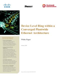
4 They can also inspect multilayer, double-sided and densely populated boards. Automated X-ray Inspection systems are referred to as testing is done once the board is completed. It often takes the form of in-circuit testing (ICT) and/or functional testing (FCT). In-circuit testing looks at the functioning of individual components after they are soldered in place. Functional testing provides a final go or no-go decision on finished PCB defectsMany things can go wrong on a PCB. Components may be misaligned. Solder connections may not be complete. Excess solder can bridge circuits and cause shorts. The chart (Figure 1, shown here) lists common PCB defects and characterizes them as structural or electrical . The different Inspection and testing methods have varying levels of effectiveness with each type of defect.
5 Page 2 Figure Industry data regarding the incidence rates of common PCB defects reveal the criticality of PCB Inspection and, in particular, of solder paste Paper # RELATEDOpen25%StructuralYesInsufficient1 8%StructuralYesShort13%StructuralYesMiss ing electrical component12%StructuralNoMisaligned8%Stru cturalYesDefective electrical component8%ElectricalNoWrong component5%ElectricalNoExcess solder3%StructuralYesMissing non- electrical component2%StructuralYesWrong orientation2%ElectricalNoDefective non- electrical component2%StructuralNoINSPECTIONI nspecting boards at various manufacturing stages allows for early detection of faults. (The earlier in the manufacturing process a defect is found, the less expensive it is to fix.) Defects can be corrected so yields at the testing stage improve.
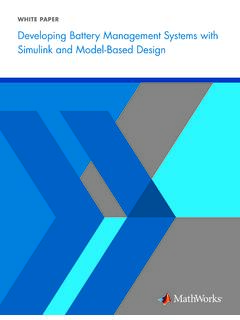
6 The most commonly used PCB Inspection systems are automated optical Inspection and automated X-ray Inspection (AXI).Automated optical Inspection (AOI)AOI is a visual Inspection method for PCBs. In an AOI system, one or more still or video cameras scan the board. The board is lit by several sources from various angles, and the machine takes images so it can build a picture of the board. Then the system compares the captured images with what the board should look like (usually based on a golden board or design specifications). AOI systems find problems like nodules, scratches and stains, as well as dimensional defects such as open circuits, shorts and thinning of the solder. They can also detect incorrect, missing and skewed components. They do all this in less time and with greater accuracy than human 3-D AOI equipment can measure component height, a weakness of traditional 2-D machines.
7 2-D machines use multi-angled colored lighting and side-angle cameras to inspect height-sensitive devices, like BGAs and leaded components, but the results are not reliable. Using 3-D Inspection allows a manufacturer to detect coplanarity on height-sensitive devices without difficulty, although shadowing may skew results for some board Well-known, accepted technology Detects many common PCB faults (See Figure 2.) Can be deployed inline at several points in the PCB manufacturing processDisadvantages Limited to line of sight, , unable to inspect hidden connections underneath BGAs and other packages Less effective inspecting densely loaded boards because some components and connections are hidden or shadowedWhite Paper #401 Page Inspection /AXI3 Surface mount technology (SMT) has allowed for smaller components and PCBs that are very densely populated.
8 Boards with more than 20,000 solder connections are not uncommon. The advent of SMT has also spawned new chip packages like BGAs and chip scale packages (CSPs) on which solder connections are not visible. These boards and chip packages cannot be inspected with the usual AOI equipment. X-ray Inspection equipment, automated (AXI) or manual, can check the solder joints under components and show defects in solder joints that may not be visible with absorb X-rays proportional to their atomic weight. Materials made of heavier elements absorb more X-rays, while materials made of lighter elements are more transparent to X-rays. Solders are made of heavy elements, such as tin, bismuth, silver, indium and lead. Most other materials on a PCB (components, substrate, etc.) are made of lighter elements, like carbon, aluminum, oxygen, hydrogen, silicon, sodium and copper.
9 In X-ray Inspection , solder shows up extremely well, while most packages, the PC board substrate, silicon integrated circuits (ICs) and component leads become barely visible. Unlike visible light used in AOI, X-rays are not reflected. Instead, they pass through objects and can form an image of the other side. X-ray Inspection systems can see through chips like BGAs for which the connections are underneath. With X-rays there is no shadowing so these systems can inspect very complex, densely packed Inspection systems provide an internal view of the solder joints, detecting bubbles that would be unseen by AOI. Also, X-ray systems can see the heels of solder joints (hidden to AOI systems because they are masked by the leads).Advantages Able to see through chip packages with connections underneath Can inspect densely packed boards Provide thorough Inspection of solder jointsDisadvantages Newer technology may not be thoroughly understood Investment may only make sense in situations in which BGAs, CSPs and similar packages are used or in which board density is beyond AOI s capabilitiesWhite Paper #401 Page a PCB is manufactured, having passed all its inspections, it is ready for testing .
10 While there are several test methods , in-circuit testing (ICT) and functional testing (FCT) are the most testing4 In-circuit test equipment measures each component to check that it is correct and in place. During ICT an electrical probe tests a populated PCB, checking for shorts, opens, resistance, capacitance and other factors to show if it was correctly made. ICT can be performed with a bed-of-nails test fixture or with a flying probe setup. A bed-of-nails tester is a test fixture with an array of small, spring-loaded pogo pins. Each pin makes contact with one node in the circuitry of the device under test (DUT). Contact is made with hundreds or even thousands of individual test points within the circuitry of the DUT when it s pressed against the pins. A bed-of-nails fixture is costly to develop and difficult to change.