Transcription of Installation & Maintenance Filter/Regulator Instructions ...
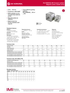
1 B72G. Installation & Maintenance Filter/Regulator Instructions B72G - - - . Port Thread Form Adjustment Drain Bowl Element Diaphragm Spring (Outlet Pressure Range) * Gauge 2 ..1/4" metal with liquid level indicator 1 ..5 m ,3 to 2 bar (5 to 30 psig) 3 ..3/8" Rc taper T ..T-bar , 1/4 turn T ..Short transparent without guard 2 ..25 m F ..0,3 to 4 bar (5 to 60 psig) G parallel automatic L ..Long transparent without guard 3 ..40 m ,3 to 10 bar (5 to 150 psig). transparent with guard * Outlet pressure can be adjusted to pressures in excess of, and less than, those specified. Do not use these units to control pressures outside of the specified ranges. technical data 3. Push bowl, or bowl with guard, into body and turn fully Fluid: Compressed air clockwise before pressurizing. 6. Maximum pressure: 4. Install a pressure gauge or plug gauge ports.
2 Gauge 7. Transparent bowl: 10 bar (150 psig) ports can also be used as additional outlets for regulated Metal bowl: 17 bar (250 psig) air. 1. Operating temperature*: 5. Plastic tube used on semi automatic drain is packed 8. Transparent bowl: -20 to +50 C (0 to +125 F) loose inside the shipping box. Push plastic tube over tip Metal bowl: -20 to +65 C (0 to +150 F) of semi automatic drain. 2 59 9. * Air supply must be dry enough to avoid ice formation at ADJUSTMENT. temperatures below +2 C (+35 F). 1. Before applying inlet pressure to Filter/Regulator , turn Particle removal: 5 m, 25 m, or 40 m filter element adjustment (1 or 7) counterclockwise to remove all force 10. 3 57. Air quality: Within ISO 8573-1, Class 3 and Class 5 on regulating spring (12). (particulates) 2. Apply inlet pressure, then turn adjustment (1 or 7). Typical flow with 10 bar (150 psig) inlet pressure, 6,3 bar 4 11.
3 Clockwise to increase and counterclockwise to decrease (90 psig) set pressure and 1 bar (15 psig) droop from pressure setting. 5. set: 38 dm3/s (80 scfm) 3. Always approach the desired pressure from a lower Manual drain connection: 1/8" 58. pressure. When reducing from a higher to a lower 12. Semi automatic drain connection: Push on 8mm (5/16") ID tube setting, first reduce to some pressure less than that Semi automatic drain operating conditions (pressure desired, then bring up to the desired pressure. 56. operated): 13. NOTE 55. Bowl pressure required to close drain: Greater than 0,1 With non-relieving filter / regulators , make pressure bar ( psig) reductions with some air flow in the system. If 16. Bowl pressure required to open drain: Less than 0,1 bar made under no flow (dead-end) conditions, the 54. ( psig) Filter/Regulator will trap the over-pressure in the Minimum air flow required to close drain: 0,5 dm3/s 14.
4 Downstream line. (1 scfm) 4. KNOB ADJUSTMENT. Push knob down to lock pressure Manual operation: Lift stem to drain bowl 15. setting. Pull knob up to release. Install tamper resistant Automatic drain connection: 1/8" cover (see Replacement Items) to make setting tamper Automatic drain operating conditions (float operated): 53. resistant. Bowl pressure required to close drain: Greater than 0,3 5. T-BAR ADJUSTMENT. Tighten lock nut (8) to lock bar (5 psig) pressure setting. Bowl pressure required to open drain: Less than 0,2 bar 52. (3 psig) SERVICING. Minimum air flow required to close drain: 0,1 dm3/s 1. Open manual drain to expel accumulated liquids. Keep ( scfm) liquids below baffle (52). Manual operation: Depress pin inside drain outlet 2. Clean or replace filter element when dirty. 18. 24. 21. Nominal bowl size: DISASSEMBLY.
5 Short bowl: 56 ml ( fluid ounce) 1. Filter/Regulator can be disassembled without removal 29. Long bowl: 65 ml ( fluid ounce) from air line. Gauge ports: 2. Shut off inlet pressure. Reduce pressure in inlet and 28. 1 8 PTF with PTF main ports outlet lines to zero. 23. Rc1/8 with ISO Rc and ISO G main ports 3. Turn adjustment (1 or 7) fully counterclockwise. 17. Materials: 4. Remove bowl - push into body and turn 26. Body: Zinc counterclockwise. 27. Bonnet: Acetal 5. Disassemble in general accordance with the item Valve: Brass numbers on exploded view. Do not remove the drains 20. Bowl: unless replacement is necessary. Remove and replace 19. Transparent: Polycarbonate drains only if they malfunction. Transparent with guard: Polycarbonate, steel guard CLEANING 25. Metal: Zinc 22. 1. Clean plastic bowl (29, 38) with warm water only.
6 Clean Metal bowl liquid level indicator lens: Transparent other parts with warm water and soap. nylon 2. Rinse and dry parts. Blow out internal passages in body Element: Sintered polypropylene 31 36A. (16) with clean, dry compressed air. Blow air through Elastomers: Neoprene and nitrile filter element (53) from inside to outside to remove 34. 37. REPLACEMENT ITEMS surface contaminants. Service Kit (includes items circled on exploded view): 3. Inspect parts. Replace those found to be damaged. 30. Replace plastic bowl with a metal bowl if plastic bowl 38. Nonrelieving ..4383-501 shows signs of cracking or cloudiness. 36. Liquid level lens kit (46, 48, 49, 50) ..4380-030 ASSEMBLY 36C. 33. filter element, 5 m (53) ..5925-03 1. Lubricate the following items with o-ring grease. filter element, 25 m (53) ..5925-01 32. 4 (Thrust washer) - outer circumference and both sides.
7 filter element, 40 m (53) ..5925-02 5, 7 (Adjusting screw) - threads and tip. 36B. Manual drain (18,19,20) (31,32,33) (40,41,42)..619-50 18, 31, 40 (Manual drain body) - the portion of the body 35. Semiauto drain (21,22,23) (34,35,36) (43,44,45) ..5379-50 that contacts the bowl, and the hole that Auto drain (24,25,26) (36A,36B,36C)..4000-50R accommodates the stem of drain valve (19, 32, 41). 50. Tamper resistant cover (knob adjustment only)..4255-51 54 (Center-post) - Bore for valve (57). 40. PANEL MOUNTING DIMENSIONS 57 (Valve) - stem. 43. 51. Panel mounting hole diameter: 40 mm ( ") 23, 28, 36, 37, 45, 50, 58, 59 - (O-rings). Panel thickness: 2 to 4 mm ( " to ") 2. Assemble the unit as shown on the exploded view. Push 39. Installation bowl, or bowl with guard, into body and turn fully 1. Shut off air pressure. Install Filter/Regulator in air line - clockwise.
8 45. vertically (bowl down), 3. Torque Table 42. with air flow in direction of arrow on body, Item Torque in Nm (Inch-Pounds) 41. upstream of lubricators and cycling valves , 2, 9 (Screw) 2,3 to 2,8 (20 to 25). as close as possible to the device being serviced. 22, 35, 44, 25, 36B (Nut) 2,3 to 2,8 (20 to 25) 49 46. 2. Connect piping to proper ports using pipe thread sealant 46 (Screw) 1,9 to 2,5 (17 to 22) 44. 48 47. on male threads only. Do not allow sealant to enter 52 (Baffle) 0,5 to 0,7 (4 to 6). interior of unit. 54 (Center-post) 0,7 to 0,9 (6 to 8). Norgren 1998. a subsidiary of IMI plc (4/98). B72G. Installation & Maintenance Instructions CAUTION. Water vapor will pass through these units and could condense into liquid form downstream as air temperature drops. Install an air dryer if water condensation could have a detrimental effect on the application.
9 WARNING. These products are intended for use in industrial compressed air systems only. Do not use these products where pressures and temperatures can exceed those listed under technical data . Polycarbonate plastic bowls can be damaged and possibly burst if exposed to such substances as certain solvents, strong alkalies, compressor oils containing ester- based additives or synthetic oils. Fumes of these substances in contact with the polycarbonate bowl, externally or internally, can also result in damage. Clean with warm water only. Use metal bowl in applications where a plastic bowl might be exposed to substances that are incompatible with polycarbonate. If outlet pressure in excess of the Filter/Regulator pressure setting could cause downstream equipment to rupture or malfunction, install a pressure relief device downstream of the Filter/Regulator .
10 The relief pressure and flow capacity of the relief device must satisfy system requirements. The accuracy of the indication of pressure gauges can change, both during shipment (despite care in packaging). and during the service life. If a pressure gauge is to be used with these products and if inaccurate indications may be hazardous to personnel or property, the gauge should be calibrated before initial Installation and at regular intervals during use. Before using these products with fluids other than air, for non industrial applications, or for life-support systems consult Norgren. Norgren 1998. a subsidiary of IMI plc (4/98).