Transcription of Installation & Programming Manual
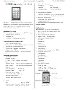
1 1 Quick Reference Refer to Quick Reference area and illustrations to identify components. Prepare door, per additional instructions (included) before installing unit. IMPORTANT: Read instructions completely before beginning the checklist below to assure completion of important steps. ATTACH CONNECTOR .. PROGRAM CODE(S) .. VERIFY OPERATION .. Section 6 Section 10 a, b, cSection 10 d1 23 45 67 89 0 Copyright 2009 Black & Decker Corporation40490-01 SmartCode Lever Manual ProgramButtonMountingHolesTurnpieceLockB uttonCylinderSettingsSwitchPanelKeypadLE DC ylinderGetting StartedInstallation & Programming ManualInteriorAssemblyInteriorCoverHalf roundSpindleExterior AssemblyLeverLatchLeverMountingPlateMoun tingBoltsInteriorAssemblyExterior Assembly22-3/8" (60mm)or 2-3/4" (70mm)1. Install latch and 1 Fig. 2d. Install strike plate onto door jamb using two small screws. Minor loose door fit may be reduced by adjusting tang. Note, the lock will not lock prop-erly if the smaller bolt of latch enters the strike hole.
2 Reposition strike plate if Determine your backset, see figure 1. b. If backset measured 2-3/4 (70mm), adjust latch as follows: Using fingers, grasp the spring pin and move it down and over to the 2-3/4 (70mm) slot. (See figure 2). For a drive in latch: Align collar opening with shape of bolt and slide it on until the catch pins of latch snap into the pin holes of collar. Install latch with the slant of bolt facing in the direction that the door closes. Use wood block to install latch. Note, should collar require removal, squeeze collar hard at sides and remove. For a latch with face plate: (1) Insert latch into backplate, (2) Insert latch and backplate into door with the slant of bolt facing in the direction that the door closes. (3) Place desired face plate over backplate and fasten with two small Prepare plateSpringPinBackplateCatch PinTangSmall BoltPin holeCollar32. Remove cover and battery Install Exterior Remove cover from assembly by sliding cover up and off, see figure.
3 3b. Remove the battery case from interior assembly by lifting the case up and out and set aside, see figure the exterior assembly flush onto door, threading the wire harness under the the connector of the wire harness though the slot at top of mounting plate. Insert the long screws to engage exterior assembly. Tighten screws to secure - making sure that both the plate and the exterior assembly are flush against the door and vertically aligned with the edge of Install Interior Mounting the half round spindle through the latch fully - to engage with the exterior Install the half round 4 Fig. 3 Important before proceeding: 1. Verify that position #2 of the Settings Switch is in the OFF posi-tion. (Refer to section 11.) 2. Work with the door open (away from jamb) to avoid accidental lock out. Wire HarnessHalf RoundSpindleConnectorLong ScrewsMounting Plate4 Important Note: To prevent damage, always handle the wire harness at the connector (do not pull wires).
4 6. Attach the Connector to the Interior PortSpindlesSmall ScrewsSpindle OpeningsInteriorAssemblyNotchSlota. Tucking any excess wire back into slot of mounting plate, place the interior assembly on door, aligning the spindles with the spindle slots of interior assembly. 7. Install Interior Once flush on door, insert and tighten small screws to secure assembly onto the mounting plate. Note: To aid insertion of screws, approach the screw holes with the screw loaded onto the screwdriver. a. Align the connector with the connector port of the interior assembly, matching notch to Once aligned, push the connector in firmly to Mount the Check both the interior and the exterior assemblies, to make sure the set screw is located on the opposite side, (the side furthest away from the latch bolt). If correctly positioned proceed to step c, if it is not on the proper side, remove and switch the set screw as directed in the following step - step b. b.
5 Using tool provided, remove set screw by unscrewing it in a clockwise direction (this is the reverse direction of what might feel normal). Reposition set screw to the other side and screw it in fully, using a counterclock direction (again this is the reverse of the normal direction).c. Install interior lever and tighten set screw Insert the key into cylinder and rotate it clockwise to the horizontal position, then press lever to seat into assembly. With key still in the horizontal position, tighten the set screw clockwise to secure the Screw (on opposite side)Latch Boltd. To install exterior lever, first remove the key from cylinder and insert the cylinder into the lever shaft, making sure the sleeve of cylinder is positioned near keyway. Note that the cylinder will not seat back fully at this time. Slide the lever on smoothly, aligning ribs inside the lever with the lever shaft (lever will not seat all the way until completing step e).CylinderSleeveShaftContinued 6 INTERIORI mportant note should you need to remove the exterior lever: 1.
6 Insert key into exterior lever and rotate clockwise to a horizontal (unlocked) position. 2. Loosen set screw and pull the lever, cylinder and key - away from keypad (6mm)2180 3 LEVER NOTES9. Install batteries Alkaline Battery WARNING: Do not dispose of in fire, recharge, put in backwards, disassemble, mix with used or other battery types. May explode or leak and cause personal Install 4 new AA Alkaline batteries into battery pack. Install the new batteries as indicated in illustration. Make sure batteries lie flat in holder. For best performance, rechargeable batteries are not recommended. AA12-+b. Install battery pack into unit as shown. Unit will beep and the LED will flash of exterior lever: When the unit is in the locked position the exterior lever is still allowed to turn, but it will not retract the latch. When the unit is in the unlocked position, the exterior lever will turn firmly, retracting the latch for Test the locking and unlocking function.
7 If you cannot lock the unit from the exterior or cannot rotate the interior turn-piece, proceed with the following steps to remedy the situation. 1. Insert the key and rotate clockwise to the horizontal position. 2. Loosen the set screw and pull the lever away from the unit, about 1/4 . 3. Rotate the key 180 clockwise. With the key remaining in the horizontal position, push the lever back to seat and tighten the set screw. 4. Test the locking and unlocking function and repeat these steps if required. Important note: This product has a panic free interior, which will allow interior lever to always retract the latch and allow exit. Caution: if you exit and plan re-entry without a key or code, make sure the turnbutton on the interior lever is in the unlocked (horizontal) position before 23 45 67 89 0 How the keypad works:Each button represents two numbers ( 1 and 2 for the first button). You only need to push the button once to get either 1 or 2.
8 For example: If your code is 1-2-5-6-8, Press the 1 2button once to get number 1. Press the 1 2button once to get number 2. Then press the 5 6button once to get number 5. Then press the 5 6button once to get number 6. Finally press the 7 8 button once to get number 23 45 67 89 010. Programming a User Code. A programmed code can be from four (4) to eight (8) digits long. For maximum security an 8 digit code is recommended. Up to 4 user codes can be entered. Excess delay in the Programming steps once started will cause unit to beep twice and will require you to restart from step (10a).Note: Programming instructions can also be found on interior of Press the program button on the interior unit Enter in 4 to 8 digit code onto the keypad. c. Press the LOCK button to save Press the program button on the interior unit Enter in 4 to 8 digit code onto the keypad. c. Press the LOCK button to save the LOCK button and re-enter the code to test.
9 Unit should go to the unlocked position allowing exterior lever to retract the latch. If it does not go to the unlock position, repeat steps (a) through (c).Press the LOCK button and re-enter the code to test. Unit should go to the unlocked position allowing exterior lever to retract the latch. If it does not go to the unlock position, repeat steps (a) through (c). Programming the 1st user the 2nd user ButtonLOCK ButtonContinued 8ON123411. SmartCode User Selectable #2 Enables the AUTO LOCK when in the ON position. With Auto Lock en-abled, SmartCode will automatically relock the door 30 seconds after #1 Status LED blinks every 5 seconds when in the ON position. Note: The low battery RED LED cannot be BatteryLockStatusRedLow BatteryHint: for easier access, use a ball point pen to operate the #4 Extra switch with NO #3 Enables the AUDIO sound (Beeper) when in the ON position. Keypad will now light red/green when buttons are Press the program button on the interior unit four Enter in 4 to 8 digit code onto the keypad.
10 C. Press the LOCK button to save Press the program button on the interior unit three Enter in 4 to 8 digit code onto the keypad. c. Press the LOCK button to save the LOCK button and re-enter the code to test. Unit should go to the unlocked position allowing exterior lever to retract the latch. If it does not go to the unlock position, repeat steps (a) through (c).Press the LOCK button and re-enter the code to test. Unit should go to the unlocked position allowing exterior lever to retract the latch. If it does not go to the unlock position, repeat steps (a) through (c). Programming the 4th user the 3rd user code. CAUTION: Prevent unauthorized entry. This lock can be opened using four different codes that are randomly set at the factory. Upon Installation and set-up, replace all of these codes with your own. Since anyone with access to the power board can change these codes, you must restrict access to the power board and routinely check both codes to assure they have not been altered without your the door is in the locked position, press the lock button to light up the keypad.