Transcription of INSTALLATION AND MAINTENANCE …
1 4. Continue with B-Vent penetrating the roof. NOTE: For Canadian 4. If your INSTALLATION terminates as oval, the Oval Flashing (MOF) and installations, use labeled ULC section, designated with Suffix G, on Oval Storm Collar (MOSC) are shown in Figure 6. An Oval Vent INSTALLATION AND MAINTENANCE vent sections exposed to atmosphere. At the roof, the opening should be 2 inches (51 mm) greater than the B-Vent OD. Above the Cap (MOC) completes the INSTALLATION . 5. Because oval vent lengths may not meet your specific run, the Oval INSTRUCTIONS FOR MODELS M & MO roof, a flashing is required to maintain the one inch ( mm) clear- ance to the combustibles of the roof. INSTALLATION of a storm collar Adjustable Length (MOA) is used to adjust for length differences. The female end of the MOA accepts the male end of the Oval GAS VENTS (B-VENT) allows water to drain over the flashing. Caulk as shown in Figure 1. 5. Install the B-Vent cap (MC) onto the B-Vent. NOTE: See height of Section.
2 When the correct length is achieved, the clamp on the MOA is tightened. The male end of the MOA snaps into the next vents under SAFETY . oval section. 6. If a UL Listed gas vent other than Metal-Fab is to be connected to 6. If, within the stud wall, a direction change is required, the 45 degree This symbol on the nameplate Round Sizes 3" (76 mm) through 14" (355 mm) the inlet end of the Metal-Fab B-Vent, use the M6A, M12A, or flat elbow (MO45F) is available. If the directional change occurs as means this product is listed by M18A gas vent adapter. Insert the male end of the other gas vent the vent is exiting the stud wall, the 45 degree standard elbow Oval Size 4" (102 mm) through 6" (152 mm) into the gas vent adapter and secure by tightening the clamp on the Underwriters Laboratories Inc. Listing No. MH7860. c adapter (See Figure 2A). If Metal-Fab B-Vent is to be inserted directly into the inlet end of a UL Listed gas vent other than Metal- (M045S) is used.
3 Increasers (MOI) are available to go from 4MO to 5MO or to 6MO. Testing No. 441 7. If the INSTALLATION is with a recessed heater, the 4 MOK INSTALLATION kit Fab, secure by using three (3) 1/4 inch ( mm) long sheet metal is required. At the top of the recessed heater mounted in the stud screws. Do not penetrate the flue (See Figure 2B). GENERAL: For installations not covered by the above, including sizes larger 7. Although it is not a preferred practice, there may be installations where wall, the gasket is applied under the base plate from the 4 MOK. The Model M and MO Gas Vents (B-Vent) have been designed for use than 12", the lowest discharge opening of the vent cap should be at The base plate is screwed to the heater outlet. The base plate has least 2' above the highest point where it passes through the roof, B-Vent must run vertically-exterior to the building and wall support is provisions to allow 4BW vent to snap in place. At the ceiling level, with gas burning Category 1 appliances.
4 A Category 1 appliance oper- needed. A wall band (MH) or (MWB) is used by placing around the B- ates with a non-positive vent static pressure and with a vent tempera- and at least 2' higher than any portion of a building within 10' hori- the ceiling plate spacers are mounted to maintain proper clear- zontally. All gas vents extending above the roof more than 5 feet Vent, then fastening to the wall. Using a wall band assures that the ances to combustibles. At this point the INSTALLATION is the same as ture that avoids excessive condensate production in the vent. clearance to combustibles is maintained (See Figure 3). must be securely guyed or braced. explained earlier (See Figure 7). B-Vent is of double wall construction, with the inner flue of aluminum 8. When the connector from the appliance is single wall, it must termi- 7. Vent sizing is defined by tables in NFPA54 (ANSI Z223-1, 1999), or alloy (allowing for rapid warmup and better draft) and the outer casing contact your Metal-Fab supplier.
5 Install in accordance with these nate into B-Vent. At this termination, it is acceptable to secure the MAINTENANCE : of galvanized steel or galvalume steel. joint with sheet metal screws. NOTE: Single wall connector, either Gas vent systems normally operate trouble free. Conduct a yearly instructions and local code requirements. Model M B-Vent is compatible with listed masonry relining systems, 8. B-Vent is to be used to vent listed gas appliances intended to burn rigid or flexible, cannot be enclosed within combustible materials. inspection of the system, and replace any damaged parts. NOTE: If single wall connectors and other listed gas vents. Model M B-Vent may only gas. Type B-Vent is NOT to be used with the following: 9. If the INSTALLATION requires two appliances to terminate into a com- extreme weather conditions occur, inspection of all exposed vent com- be used to reline masonry chimneys (Separate instructions are avail- mon B-Vent, a B-Vent wye or tee is used.)
6 It is recommended that ponents is necessary. Replace any damaged parts. able from Metal-Fab). A. Unlisted Gas Appliances B. Incinerators the higher output appliance, normally the furnace, insert into the Model MO, Oval Gas Vent is designed for INSTALLATION within 2" x 4" or C. Recessed Heaters bottom of the wye or tee and the other appliance attach to the tap. 2" x 6" wall studs and for venting of wall mounted furnaces. Transition D. Conversion Burners To minimize the length of run and to provide maximum flexibility in INSTALLATION INTERCONNECTIONS DETAIL 1. from oval to round for lowest cost INSTALLATION is easily obtained. these installations, a swivel tee (MST) or swivel wye (MSY) is used. E. Gas/Oil Burners These components provide 360 degrees of rotation to position the F. Any appliance which may be readily converted to a solid or SAFETY: liquid fuel. tap in the proper orientation (See Figure 4). NOTE: Consult the CAUTION: UL listing is based on using B-Vent components sup- Metal-Fab catalog for the many variations of wyes and tees avail- G.
7 Any other appliance NOT intended to burn only gas. plied by Metal-Fab, Inc. Performance may be affected and a safety able. In areas where solid or liquid fuels are common, the vent location 10. It is a common practice to utilize the 90 degree adjustable elbow hazard created if parts shown in these instructions are not used. should be marked For use with vented appliances burning only 1. Metal-Fab B-Vent pipe and fittings were designed and are listed to gas . (M90) in the appliance area to minimize vent run. Use of the M90 or >. form a continuous passageway from the gas burning appliance to M45/60 elbow is acceptable and not limited to the appliance area. 9. Venting into an unlined masonry chimney may cause condensation. 11. For horizontal and lateral runs, it is recommended that support be the vent termination above the roof, including the vent cap. Install B-Vent or Metal-Fab metal liner inside the chimney to pre- used every 5 feet (1524 mm). Plumbers straps are commonly used.
8 2. These B-Vent components are to be installed with minimum one vent condensation. They should be positioned to maintain the 1 inch ( mm) clear- inch clearance to combustible material. Strap vent in place, espe- 10. When installing exterior vent, not enclosed by the structure or a ance to combustibles. cially on lateral or horizontal runs, to maintain proper clearances to chase, consult local gas utility, appliance manufacturer, and/or combustible. Do not pack insulation or other materials around the 12. If your INSTALLATION requires a change in diameter due to vent capaci- Line up the pipe ends. Push the ends of the pipe together. authority having jurisdiction. ty, a B-Vent increaser (MI) is available. INSTALLATION is the same as B-Vent. 11. If a power vent fan is used, make sure it is located at the terminus standard B-Vent Sections. 3. When installing B-Vent always align Up arrow away from appli- (exhaust end) of vent system, so as to maintain negative pressure ance.
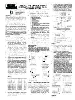
9 Oval Vents within the vent. The 4MO and 5MO oval vents are listed for use in either 2" x 4" or 2" x 4. Locate vent as close as possible to appliance to obtain maximum 12. A B-Vent support plate (MSP) is required if vertical height exceeds 6" stud walls, with firestop/spacer to maintain proper clearance to com- draft and minimize connector pipe length. 30 feet. Maximum of 30 feet between supports. bustibles. The 6MO is listed for use in a 2" x 6" stud wall. The 5. For horizontal runs, maintain a pitch or rise from the appliance. INSTALLATION : firestop/spacer is to be located centrally between studs spaced not less Minimum rise is 1/4 inch ( mm) per foot (305 mm). than 16" on centers. The oval vent is interlocked by pushing together. >. Round B-Vent 6. A B-Vent Cap should be used on all installations to prevent back The Type M B-Vent sections and components 3"-14" diameter use the See Detail 2. The 4MO has a dual listing as MO and BW oval vent. The drafts and to keep out rain and debris.
10 The vent must extend Metal-Fab positive twist lock for interconnections. Align the ends of the 4BW is used with recessed heaters with maximum output of 85000. through a flashing, and should terminate with the lowest discharge vent, push together then twist section to lock in place. Use SureLock BTU/HR (25 KW) for single story and 65000 BTU/HR (19 KW) for multi- opening no closer to the roof than the minimum height shown in the tab on 3"-6". See Detail 1. No additional fasteners are required to story installations. table below. These minimum heights may be used provided the assure a safe INSTALLATION . It is acceptable to apply screws at the joints if 1. Normally the appliance outlet is of a round shape. Therefore, a B- vent is not less than 8' from any vertical wall: local code requires, or at the installing contractor's option, provided that Vent Section or Drafthood connector (MDC) will be attached to the Twist to engage twist lock. Depress the SureLock tab to appliance.