Transcription of Installation and Maintenance Guide for NIBCO …
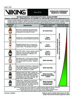
1 AHEAD OF THE FLOW 06/03/2009 AHEAD OF THE FLOW BFVMAN-0609 2009, NIBCO INC. printed in USA Installation and Maintenance GuideforNIBCO butterfly valves with Rubber SeriesLD1000/2000/7000/8000 SeriesLD/WD2000/3000/5000 SeriesLC/WC2000 SeriesLD/WD3500 SeriesFC/FD2000 SeriesFC/FD5000 SeriesN200 SeriesAHEAD OF THE FLOW INC. WORLD HEADQUARTERS 1516 MIDDLEBURY ST. ELKHART, IN 46516-4740 USA PH: TECH SERVICES PH: FAX: INTERNATIONAL OFFICE PH: + FAX: + 06/03/2009 Installation Guide FOR NIBCO butterfly VALVESI. SHIPMENT & STORAGENIBCO butterfly valves are individually boxed thru the 12" size. The 14" through 60" butterfly valves are shipped individually with the faces covered using cardboard or plywood to protect the flange sealing disc is shipped in the nearly closed position to protect the sealing edge and prevents the liner from taking a temporary set.
2 The stem bushings and disc edge have been coated with a factory-applied lubricant to prolong storage and service may be shipped or stored in any position. Storage should be limited to 10 years indoors with a temperature range of 40 F to 90 butterfly VALVE Installation GUIDELINESNIBCO butterfly valves are bi-directional and may be installed with flow in either , lug and wafer style valves are designed and suitable for Installation between ANSI Class 125 or 150 flanges. Cast iron flat-face, steel raised-face, both slip-on and weld-neck, and bronze or plastic flanges may be used (See Table I below). Generally raised face flanges should not be used with cast iron lug style valves ( NIBCO N2002 and LC2000 series valves ). Because of the unique seat design, NIBCO (2"-48") butterfly valves do not require the use of flange gaskets and can be used for dead end service without a down-stream flange.
3 Grooved style valves connect to metallic pipe of IPS per AWWA valve can be installed in any horizontal or vertical position. If a choice of stem positions exists, the valve should be installed with the stem in the horizontal position; this will minimize seat wear by distributing the stem and disc weight evenly. Also, if the media is abrasive, the horizontal stem position is highly valves have been designed so that the disc, in the open position, will clear the inside diameter of schedule 40 and 80 steel pipe. Care should be taken when installing a butterfly valve adjacent to lined pipe, as-cast fittings, or schedule 80 plastic pipe. In some cases the disc in the opened position will interfere with the adjacent valves should be installed a minimum of six (6) pipe diameters from other line components.
4 This is not always practical but it is important to design in as much distance as possible. Interference may occur when valves are installed directly to the outlet flange of a swing check, silent check, or reducing flange. Check valve and butterfly valve combinations are very popular; normally a short spool piece is required between the OF THE FLOW INC. WORLD HEADQUARTERS 1516 MIDDLEBURY ST. ELKHART, IN 46516-4740 USA PH: TECH SERVICES PH: FAX: INTERNATIONAL OFFICE PH: + FAX: + 06/03/2009 Valve LD/WD/LC/WC LD7000/8000 Series N200 Series Series 1000/2000/3000/5000 Minimum Maximum Minimum Maximum Minimum Maximum Valve Pipe/Flange Pipe/Flange Pipe/Flange Pipe/Flange Pipe/Flange Pipe/Flange Size ID for Disc ID for ID for Disc ID for ID for Disc ID for Clearance Proper Seal Clearance Proper Seal Clearance Proper Seal 2 21/2
5 3 4 5 6 8 10 12 14 16 18 20 24 28
6 30 32 36 42 48 54 60 TABLE IPiping/Flange Inside Diameter RequirementsWhen using a valve with gear operator attached, it may be desirable to have the hand wheel positioned to allow easy access, or for use of an optional adjustable sprocket rim (chain wheel) for remote operation. Before valve Installation , please review Gear Operator Installation and Handwheel Positioning section on page 3 of this booklet.
7 These instructions illustrate how to orient the gear operator handwheel position in relation to the valve body and piping system. Pre-planning may save from having to remove a "just installed" valve and re-installing in another orientation. II. butterfly VALVE Installation GUIDELINES OF THE FLOW INC. WORLD HEADQUARTERS 1516 MIDDLEBURY ST. ELKHART, IN 46516-4740 USA PH: TECH SERVICES PH: FAX: INTERNATIONAL OFFICE PH: + FAX: + 06/03/2009 III. GEAR OPERATOR Installation HANDWHEEL POSITIONING TABLE 2 INSTALLATION1. Install handwheel (1) onto gear operator shaft and secure with pin (2). (If not already attached) See Fig. Turn the handwheel (1) clockwise until in full SHUT Remove 2 screws holding pointer cover plate to center of gear operator to expose bore.
8 Retain pointer cover plate and screws for reinstallation Assure valve is in full SHUT position, turn valve stem (5) to close disc if Assure both mounting base of gear operator (3) and valve top flange (6) are clean and Determine desired handwheel position in reference to the piping system and compare with Fig. 2. There are 2 mounting positions for the gear operator onto the valve and the valve can be mounted in either direction into the piping system. This will allow handwheel to be positioned in any of the 4 quadrants as shown in Fig. 2. Note that all Fire Protection and 10" and 12" size commercial valves only allow for handwheel positioning in quadrants 1 and ) Gear operators with adapter bushing. Insert adapter bushing (4) into gear operator (3) bore aligning bushing key with desired keyway.
9 Keyway selection will determine handwheel orientation posi-tion. (Note that Fire Protection model adapter bushings differ from illustration and only have 1 keyway position). Align adapter bushing (4) bore with valve stem (5) and slide gear operator assembly onto valve stem (5) until seated with valve top ) Gear operators without adapter bushing. Align gear operator (3) bore with valve stem (5) and align with desired keyway. Keyway selection will determine handwheel orientation position. Slide gear operator assembly onto valve stem (5) until seated with valve top Secure gear operator (3) to valve top flange (6) using supplied* fasteners (7 & 8). 9. Reinstall pointer cover plate onto gear operator removed in step 3 above. Arrow should be aligned to indicate SHUT Install flag and secure with Allen Screw.
10 (Fire Protection gear operators only.)11. Rotate handwheel from full SHUT to Full OPEN positions several times to assure proper operation. See Stop Adjustment Procedure section of this instruction booklet on page 5 if stop alignment adjustment is Proceed with valve Installation into piping Fire Protection, gear operators, it is critical to use only the key supplied with gear operator in order to conform to UL, FM and ULC : Connection of gear operator to valve stem varies depending on gear operator model, size and style. The adapter bushing and key may be different from illustration shown.*A minimum of two fasteners is required, installed in opposite diagonal Required Fire Protection 2" 8" 9/16" hex wrench & 1/8" hex allen wrench (UL/FM) 10" 12" 3/4" hex wrench and 1/8" hex allen wrench 2" 8" 9/16" hex wrench Commercial 10" 14" 3/4" hex wrench 16" 18" 11/8" hex wrenchFig.