Transcription of Installation and Operating Instructions - …
1 Installation andOperating InstructionsVacuum PumpsR 5 KB/KC 0040 DBusch Produktions GmbHSchauinslandstr. 179689 MaulburgGermany0870152113 /110524 / Original Instructions / Modifications reservedTable of ContentsPreface .. 2 Technical Data .. 2 Product Description .. 3 Use .. 3 Principle of Operation .. 3 Oil Circulation .. 3 Cooling .. 4 Start Controls .. 4 Safety .. 4 Intended Use .. 4 Safety Notes .. 4 Emission of Oil Mist .. 4 Noise Emission .. 4 Transport .. 4 Transport in Packaging .. 4 Transport without Packaging .. 4 Storage .. 5 Short-term Storage .. 5 Conservation .. 5 Installation and Commissioning .. 5 Installation Prerequisites .. 5 Mounting Position and Space .. 5 Suction Connection .. 6 Gas Discharge .. 6 Electrical Connection / Controls.
2 6 Installation .. 7 Mounting .. 7 Connecting Electrically .. 7 Connecting Lines/Pipes .. 7 Filling Oil.. 7 Recording of Operational Parameters .. 8 Operation Notes .. 8 Use .. 8 Conveying Condensable Vapours .. 8 Maintenance .. 9 Maintenance Schedule .. 9 Daily: .. 9 Weekly: .. 9 Monthly: .. 9 Every 6 Months: .. 9 Every Year: .. 9 Every 500 - 2000 Operating Hours: .. 9 Checking the Oil .. 9 Checking the Level .. 9 Topping up Oil.. 9 Checking the Colour of the Oil .. 10 Oil Life .. 10 Oil Change .. 10 Draining Used Oil.. 10 Flushing the Vacuum Pump.. 10 Filling in Fresh Oil.. 10 Exhaust Filter .. 10 Checks during Operation .. 10 Assessment .. 11 Change of the Exhaust Filter .. 11 Removing the Exhaust Filter .. 11 Inserting the Exhaust Filter.
3 11 Overhaul .. 11 Removal from Service .. 12 Temporary Removal from Service .. 12 Recommissioning .. 12 Dismantling and Disposal .. 12 Troubleshooting .. 13 Exploded View .. 18 Spare Parts .. 19 Spare Parts Kits .. 20 Accessories .. 20 Oil .. 20EC-Declaration of Conformity .. 21 Busch All over the World in Industry .. 22KB/KC 0040 DPreface0870152113 / 110524page 2 PrefaceCongratulations on your purchase of the Busch vacuum pump. Withwatchful observation of the field s requirements, innovation and steadydevelopment Busch delivers modern vacuum and pressure Operating Instructions contain information for product description, safety, transport, storage, Installation and commissioning, maintenance, overhaul, troubleshooting and spare partsof the vacuum the purpose of these Instructions , handling the vacuum pumpmeans the transport, storage, Installation , commissioning, influence onoperating conditions, maintenance, troubleshooting and overhaul ofthe vacuum to handling the vacuum pump these Operating Instructions shallbe read and understood.
4 If anything remains to be clarified pleasecontact your Busch representative!Keep these Operating Instructions and, if applicable, other pertinentoperating Instructions available on DataNominal suction capacity(50Hz/60Hz)m /h40 / 48 Ultimate pressurehPa (=mbar) 0040 D: 2KC 0040 D: 20 Motor nominal rating(50Hz/60Hz) nominal speed(50Hz/60Hz)min 13000 / 3600 Sound pressure level(EN ISO 2151) (50Hz/60Hz)dB (A)69 / 71 Operating temperature(50Hz/60Hz) C80 / 85 Ambient temperature range C12 .. 30 Ambient pressureAtmosphericpressureOil approx. (50Hz/60Hz)kg~29 Product DescriptionUseThe vacuum pump is intended for the suctionof air and other dry, non-aggressive, non-toxic and non-explosivegasesConveying media with a lower or higher density than air leads to an in-creased thermal and/or mechanical load on the vacuum pump and ispermissible only after prior consultation with case the vacuum pump is equipped with a gas ballast (optional) wa-ter vapour within the gas flow can be tolerated within certain limits( page 8: Conveying Condensable Vapours).
5 The conveyance ofother vapours shall be agreed upon with vacuum pump is intended for the placement in a non-potentiallyexplosive vacuum pump is thermally suitable for continuous operation(100 percent duty).The vacuum pump is ultimate pressure of OperationThe vacuum pump works on the rotating vane circular rotor is positioned centrically on the shaft of the vacuumpump ( drive motor shaft).The rotor rotates in an also circular, fixed cylinder, the centreline ofwhich is offset from the centreline of the rotor such that the rotor andthe inner wall of the cylinder almost touch along a line. Vanes, slidingin slots in the rotor, separate the space between the rotor and the cyl-inder into chambers. At any time gas is sucked in and at almost anytime ejected. Therefore the vacuum pump works almost pulsation order to avoid the suction of solids, the vacuum pump is equippedwith a screen in the suction order to avoid reverse rotation after switching off, the vacuumpump is equipped with a non-return : This valve shall not be used as a non-return valve or shut-offvalve to the vacuum system and is no reliable means to prevent suctionof oil into the vacuum system while the vacuum pump is shut case the vacuum pump is equipped with a gas ballast (optional):Through the gas ballast a small amount of ambient air is sucked intothe pump chamber and compressed together with the process gas.
6 Thiscounteracts the accumulation of condensates from the process gas in-side the vacuum pump ( page 8: Conveying Condensable Vapours).The gas ballast line is equipped with a sinter metal order to improve the Operating characteristics the outlet of thepump chamber is equipped with a spring loaded CirculationThe vacuum pump requires oil to seal the gaps, to lubricate the vanesand to carry away compression oil reservoir is located on the pressure side of the vacuum pump( high pressure) at the bottom of the bottom chamber of the feed openings are located on the suction side of the vacuum pump( low pressure).Forced by the pressure difference between pressure side and suctionside oil is being drawn from the oil separator through the oil supplylines and injected on the suction with the sucked gas the injected oil gets conveyed throughthe vacuum pump and ejected into the oil separator as oil mist.
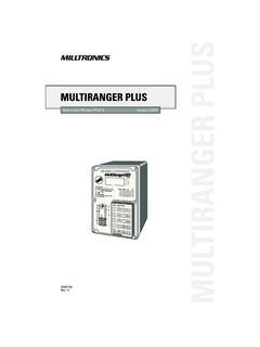
7 Oil thatseparates before the exhaust filter accumulates at the bottom of thebottom chamber of the oil that is separated by the exhaust filter accumulates at the bottom ofthe upper chamber of the oil flow resistance of the exhaust filters causes the inside of the ex-haust filters (which is connected to the bottom chamber of the oil sep-arator) to be on a higher pressure level than the outside of the exhaustfilters ( the upper chamber of the oil separator). Because of thehigher pressure in the bottom chamber it is not possible to let oil thatdrips off the exhaust filters simply flow down to the bottom with oil return line to the suction connection (KC 0040 D):Therefore the oil that accumulates in the upper chamber is suckedthrough the oil return line right to the suction with oil return line to the B-cover (KB 0040 D):Therefore the oil that accumulates in the upper chamber is suckedthrough the oil return line right to the cylinder 0040 DProduct Description0870152113 / 110524page 3aOil drain plugbOil sight glasscOil fill plugdNameplateeTerminal boxfEye boltgSuction connectionhGas dischargeIAxial flow fanCoolingThe vacuum pump is cooled by radiation of heat from the surface of the vacuum pump incl.
8 Oilseparator the air flow from the fan wheel of the drive motor the process gas the air flow from the fan wheel (i) on the shaft of the vacuumpumpStart ControlsThe vacuum pump comes without start controls. The control of thevacuum pump is to be provided in the course of UseDefinition: For the purpose of these Instructions , handling thevacuum pump means the transport, storage, Installation , commission-ing, influence on Operating conditions, maintenance, troubleshootingand overhaul of the vacuum vacuum pump is intended for industrial use. It shall be handledonly by qualified allowed media and operational limits ( page 3: Product De-scription) and the Installation prerequisites ( page 5: InstallationPrerequisites) of the vacuum pump shall be observed both by themanufacturer of the machinery into which the vacuum pump is to beincorporated and by the maintenance Instructions shall be to handling the vacuum pump these Installation and operatinginstructions shall be read and understood.
9 If anything remains to beclarified please contact your Busch representative!Safety NotesThe vacuum pump has been designed and manufactured according tostate-of-the-art methods. Nevertheless, residual risks may Operating Instructions highlight potential hazards where appro-priate. Safety notes are tagged with one of the keywords DANGER,WARNING and CAUTION as follows:DANGER_aDisregard of this safety note will always lead to accidents with fa-tal or serious of this safety note may lead to accidents with fatal or se-rious of this safety note may lead to accidents with minor inju-ries or property of Oil MistCAUTION_aThe non-OEM spares market offers exhaust filters that are geomet-rically compatible with Busch-vacuum pumps, but do not featurethe high retention capacity of genuine Busch-exhaust risk of damage to order to keep the emission on the lowest possible level only gen-uine Busch-exhaust filters shall be oil in the process gas is separated to the greatest possible extent.
10 But not gas conveyed by the vacuum pump contains remainders of of process gas over extended periods can be room into which the process gas is discharged must be suffi-ciently : The possibly sensible smell is not caused by droplets of oil,though, but either by gaseous process components or by readily vola-tile and thus gaseous components of the oil (particularly additives).Noise EmissionFor the sound pressure level in free field according to EN ISO 2151 page 2: Technical vacuum pump emits noise of high of damage to the staying in the vicinity of a non noise insulated vacuumpump over extended periods shall wear ear : Also a vacuum pump, that is not topped up with oil contains res-idues of oil (from the test run). Always transport and store the vacuumpump in upright position.