Transcription of INSTALLATION AND OWNERS MANUAL - bradfordwhite.com
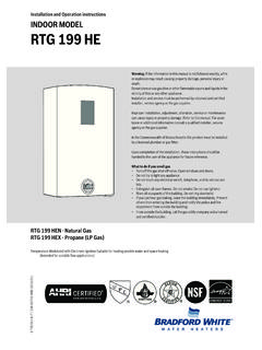
1 1 INSTALLATION AND OWNERS MANUAL WARNINGBEFORE ATTEMPTING INSTALLATION OF THIS UNIT OR MAKING ANY ADJUSTMENTSTO THE UNIT ALWAYS BE SURE MAIN CIRCUIT BREAKER IS OFFTO PREVENT DANGEROF SERIOUS ELECTRIC :SERIAL NO : INSTALLATION DATE :ELEMENT RESISTANCE: OHMSSWITCH ON FLOW RATE: GPMOPERATING TEMPERATUREMIN: MAX:INSTALLER/ CONSUMER RESPONSIBILITIESPLEASE TAKE THE TIME TO READ NOT ONLY THIS MANUAL BUT ALSO THEWARRANTY CARD ENCLOSED. WARRANTY OF THIS HEATER WILL DEPEND ON PROPERINSTALLATION, OPERATION, AND REQUIRED MAINTENANCE. THE WARRANTY SHALL BEVOID IF THE DESIGN OR STRUCTURE OF THE WATER HEATER HAS BEEN ALTERED IN ANY WAY WHATSOEVER. THE MANUFACTURER OF THIS WATER HEATER WILL NOT BELIABLE FOR ANY DAMAGES BECAUSE OF FAILURE TO COMPLY WITH THE INSTALLATIONAND OPERATING INSTRUCTIONS OUTLINED ON THE FOLLOWING YOU REQUIRE ANY HELP OR HAVE ANY QUESTIONS RELATING TO THEINSTALLATION OR PERFORMANCE OF THIS HEATER, PLEASE CONTACT TECHNICAL SERVICE TOLLFREE : THE INFORMATION LISTED BELOW BEFORE VOLT 3 PHASE DELTAELECTRIC INSTANTANEOUS WATER HEATERMODELS: EFTR-18000-6-T-10, EFTR-24000-6-T-10, EFTR-32000-6-T-10 BRADFORD WHITE MIDDLEVILLE, MI 49333 800-334-33932 ModelNumberVolts(delta)3 wireMax.
2 Output @ 480 VAmpsPer :ML: Multi-lav( gpmactivation, temperature set at 110 degrees)S: Sanitation (Temperature -180 degrees)MODEL NUMBERS COVEREDU nless otherwise noted, all above units have the following flow rate and temperature specifications as factory standard settings:FLOW RATESTurn-on GPM / Maximum 4 GPMTEMPERATURES tandard preset 140 degrees F3 GENERALTo obtain optimum performance and energy savings, the unit should be located as near as possible to the point of use. The unit must only be installed in a vertical position with the inlet and outlet at the power is activated by individual electronic flow switches located in each of the three heating modules. These modules will be damaged by excessive heat; do not solder any pipes that are in contact with the ensure pipes are clear of INSTALLATION debris before fitting the heater, otherwise the flow switches could jam in the on position.
3 The unit must be connected to its own individual electric circuit protected by a suitably rated three pole breaker. The maximum voltage which can beapplied across any heating module is 480 volts. WARNINGI mproper INSTALLATION , adjustment, alteration, service or maintenance can cause DEATH,SERIOUS BODILY INJURY OR PROPERTY DAMAGE. Refer to this MANUAL forassistance or consult the local electric utility for further unit is supplied with 1/2 compression water no circumstances use a propane or plumber s torch on pipe which is connected to the heater, as serious damage to the electronic flow switch will result. Do not use pipe to ground the system may result in death or serious injury. 4 MOUNTING THE UNIT1) The unit should be mounted as close to the point of use as ) This unit must only be mounted in the vertical position with the water fittings located at the bottom of the unit.
4 Mounting other than in the vertical position WILL cause element burn ) The cold water inlet is on the right hand side and the hot water outlet is on the left hand NOcircumstances can these be ) Leave a minimum of 8 above the unit for easy replacement of the ) The heater should be fixed to the wall using all 4 mounting holes of the back plate. Unit weight is approximately 15 lbs. Use an appropriate fastener for this weight. For the unit to be mounted against hollow walls, suggest using steel wall anchors with the correct grip range and #6-32 screw size ) The unit should be installed in the plumbing system in such a way that there is no tendencyfor the unit to be starved of water. For example: an excessive draw-off of cold water justbefore the unit. Also do not fit an unrestricted hot water draw-off point below the heater asthis will tend to empty the heater by siphoning.
5 NOTEALL MOUNTING AND PLUMBING MUST BE COMPLETE BEFORE YOU PROCEEDWITH ELECTRICAL HOOK-UP. TEST THE INSTALLATION FOR LEAKS BEFORE CONNECTING THE ELECTRICAL Locations -Nonincendive Type Installation1) The unit can be mounted in an approved NEMA4 ) Non-incendive for Class I, Division 2, Groups A, B, C & D. Temperature class: T5 (212 F)3) As to INSTALLATION , refer to the National Electrical Code and NFPA 70. For locations C1, refer to section 501-4 (wiring methods) and 501-10 (utilization equipment) : If ignition atmosphere is <T5 class, or if other classifications are required, another method of compliance would be Purged and Pressurized . This is the process of supplying an enclosure with a protective gas at a sufficient flow and positive pressure to reduce the concentration of any flammable gas or vapor initially present to an acceptable level.
6 For further information, see ANSI/NFPA 496-1998, Purged and Pressurized Enclosures for Electrical ) The unit is supplied with compression fittings. DO NOT USE PIPE DOPE AND DONOT SOLDER PIPE TO THE INLET OR ) Take care to ensure that the pipes are correctly aligned with the inlet and outlet bosses in order to avoid excessive stress on the heater :When soldering pipe joints remove heater from the wall. Serious damage can occurif any soldering is done while pipes are connected to the water through the supply pipe to remove all debris from the pipe before connecting theheater. Failure to do so could cause damage to the flow ) Install isolating valves (full flow ball valve type) on bothinlet and outlet pipes. This allowsunit to be isolated for maintenance purposes. 4) When all plumbing is complete, fully check the system for water leaks at all plumbing connections.
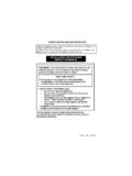
7 If leak is present take corrective action. Fully open both inlet and outletball valves. Run all hot water outlets fed by this heater one at a time for a minute or twountil the water flow is continuous, free from gulping and from all visible air pockets. PLUMBING HOOK-UPNOTEALL MOUNTING AND PLUMBING MUST BE COMPLETE BEFORE YOU PROCEEDWITH ELECTRICAL THE INSTALLATION FOR LEAKS BEFORE CONNECTING THEELECTRICAL Hot outlet1/2 Compression fittingDO NOTSOLDERCold inlet1/2 CompressionfittingDO NOTSOLDER6 ELECTRICAL HOOK-UPWARNINGHAZARD OF ELECTRICAL SHOCK! BEFORE BEGINNING ANY WORK ON THEINSTALLATION, MAKE SURE THE ELECTRICAL SUPPLY TO THE HEATER IS TURNED OFF . FAILURE TO DO THIS COULD RESULT IN DEATH, SERIOUS BODILY INJURY,OR PROPERTY DAMAGE. WARNINGWATER HEATERS EQUIPPED FOR ONE VOLTAGE ONLY: CHECK THE RATING PLATE ON THE FRONT OF THE UNIT. DO NOT USE THIS WATER HEATER WITH ANY VOLTAGEOTHER THAN THE ONE SHOWN ON THE MODEL RATING PLATE.
8 FAILURE TO DO SO CAN RESULT IN DEATH, SERIOUS BODILY INJURY, OR PROPERTY DAMAGE. IF YOUHAVE ANY QUESTIONS OR DOUBTS CONSULT YOUR ELECTRIC heater must have its own independent circuit using four wires; three live and one earth ground,of the appropriate rating protected by the correctly rated three pole breakerWARNINGFAILURE TO GROUND THE SYSTEM MAY RESULT IN DEATH OR SERIOUS INJURYR atings of Electric Tankless Water HeaterTHIS UNIT MUST NOTBE CONNECTED IN STAR CONFIGURATIONT emperature Rise (F ) GPM(gallons per minute) Model number prefixkW RatingAmps per phase2gpm3gpm4 YOUR HEATERIMPORTANTB efore switching on the power at the main circuit breaker panel make sure that the hotwater circuit is free of air pockets or premature failure of the heating element will do this open all hot water fixtures one at a time for several minutes until the water flowis continuous and free from gulping and from visible air ) With inlet and outlet BALL VALVES fully open, turn on a hot water ) Run for 3 ) Switch on electric supply at circuit breaker )
9 The power indicator lights should now come : At this point water temperature may not be hot. 5) Using the OUTLET BALL VALVE slowly reduce water flow until desired temperature isachieved at hot water outlet. NOTE:The water temperature is regulated by the flow through the heater. The lower theflow the higher the temperature and vice ) If water does not achieve desired temperature, please call technical : NO HEAT -INDICATOR LIGHT OFF1) ELECTRIC SUPPLY IS OFFTurn on the main circuit ) NO OR LOW WATER FLOW Ensure that the minimum flow rate to turn on your heater is met, for this figure refer to page 2 of this check that the inlet filter screen is clear from any ) WATER CONNECTIONS ARE REVERSEDCold water inlet = right side, hot water outlet = left ) ELEMENT BURNED OUTTURN OFF THE MAIN BREAKER!Using an ohmmeter test the resistance of the heating element across the two threaded termination rods on top of the the front cover of this MANUAL for the correct the resistance is much greater than the correct value, call your supplier for a replacement : NO HEAT OR LOW TEMPERATURE WITHINDICATOR LIGHT ON1) WATER FLOW TOO HIGHR educe the water flow by using an outlet ball valve.
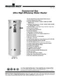
10 See page 6 for temperature rise at various flow ) INCORRECT POWER SUPPLYMake sure that the unit is connected to the voltage supply specified on the rating label on the front cover of the unit and no ) ELEMENT BURNED OUTTURN OFF THE MAIN BREAKER!Repeat the steps from paragraph 4 )THERMOSTAT ADJUSTMENT SCREW NOT TURNED UPTurn the thermostat adjustment screw clockwise in small increments until the indicator light remains on. Take care not to force the screw past it s stop PARTS DIAGRAMHEATER CORE ASSEMBLY (PLEASE SPECIFY 480 VOLTS ON ANY ORDERS)FOR EFTR-18000 part # EX3454 FOR EFTR-24000 part # EX2880 FOR EFTR-32000 part # EX2194 THERMOSTATICPCBPART# EX100CV-480V(1 required)SLAVE part #EX100S-480V(2 required)TRIACPART# EX18 Contactor part #EX08002-01(480 volts)L1