Transcription of INSTALLATION AND SETUP GUIDE - secalarm.com
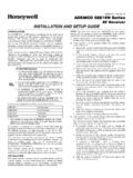
1 K3590-ADV3 3/06 Rev. A ADEMCO 6150 & 6160 ADEMCO 6150 & 6160 ADEMCO 6150 & 6160 ADEMCO 6150 & 6160 REMOTE KEYPADSREMOTE KEYPADSREMOTE KEYPADSREMOTE KEYPADSINSTALLATION AND SETUP GUIDE Keypad Features ADEMCO 6150 Fixed-Word ADEMCO 6160 2-Line Alpha Backlit Display (see note) (see note) Dedicated Function Keys Built-in Sounder Piezo Speaker Note: Permanent display backlighting is an option on some controls (see the control's instructions for details). GENERAL INFORMATION The ADEMCO 6150 and ADEMCO 6160 are addressable Remote Keypads designed for use with ADEMCO control panels. Addresses are set via the keypad keys.
2 The keys on the keypads are continuously backlit for convenience. KEYPAD DISPLAYS AND LEDS The keypads have the following display features: Model Fixed Word Display 2-line Alpha Display 2-digit Zone Identifier Custom Zone Descriptors 6150 X X 6160 X X The following table shows the LEDs and their functions: LED Function Red Lights when the system is armed in any mode Green Lights when the system is "ready" to be armed. SPECIAL FUNCTION KEYS The keypads also feature function keys.
3 These keys may be programmed for panic alarms or other special functions such as macros. See the control's instructions for details. Function keys must be held down for at least 2 seconds to activate an alarm; key pairs are activated immediately. Function Keys A or [1] and [ ] B or [ ] and [#] C or [3] and [#] D WIRING AND INSTALLATION The keypads can be surface mounted directly to a drywall, or to a single- or double-gang electrical box. 1. Push the two case release snaps at the bottom of the keypad with the blade of a medium screwdriver (this will push in the release snap), then pull that side of the case back away.
4 Insert the screwdriver in the side of the keypad (between the front and back case) and gently twist to release the side locking tab. Repeat for the other side. Refer to Figure 1 for location of the case back release snaps and locking tabs. 2. Route wiring from the control panel through the opening in the case back. 3. Mount the case back to a wall or electrical box. 4. Wire directly from the keypad s terminal block to the terminal block on the control panel as follows: Wiring Table (All Keypads) Keypad Control Panel Wire Color G Data In Green Aux Pwr (GND) Black + + Aux. Pwr Red Y Data Out Yellow See the control panel s INSTALLATION and SETUP GUIDE for more complete details.
5 5. Reattach the keypad to its case back. NOTE:TO REMOVE CASE BACKPUSH IN THE TWO MOUNTINGSNAPS LOCATED ALONG THE BOTTOM OF THE KEYPADAND LIFT B Figure 1. Removing the Case Back SETTING THE KEYPAD ADDRESS The keypad can either be set for an address of 00-30, or to the non-addressable mode (31). The keypad's default address is 31. To change the keypad's address, do the following: 1. Enter address mode: Power up the keypad. Within 60 seconds of power-up, press and hold down the [1] and [3] keys at the same time for 3 seconds. (If unable to enter address mode, power up and try again.) The current keypad address will be displayed, and the cursor will be under the "tens" digit.
6 If 10 seconds have passed with no key entry, the keypad automatically exits address mode. You must power down, power up and start address mode again. NOTE: The keypad will not enter address mode if the panel to which it is connected is in programming mode. 2. Set the current address to "00": Press [0] to clear the current "tens" digit. The cursor will move to the "ones" digit position. Press [0] to clear the current "ones" digit. The cursor will move back to the "tens" digit position. 3. Enter the keypad's address: Enter the proper "tens" digit of the keypad's address. The cursor will move to the "ones" digit position.
7 Enter the proper "ones" digit of the keypad's address. Note that address "31" sets the keypad to non-addressable mode. 4. Exit address mode: Press [ ] to save the displayed address and exit address mode. VIEWING THE KEYPAD ADDRESS Press and hold down the [1] and [3] keys at the same time for about 3 seconds. The current address is displayed. No key entry is allowed. Press any key to exit or wait 10 seconds to exit viewing mode. FUNCTION KEY LABELS A set of adhesive-backed labels with some typical function symbols ( , fire, police, personal emergency, etc.) is provided. These labels can be placed on or next to the keys to identify each key's function for the end user (as determined by the control panel's capability and programming; see the control's instructions).
8 SPECIFICATIONS Physical: 6150: 4-7/8"H x 6-1/4"W x 1"D 6160: 5-5/16"H x 7-3/8"W x 1-3/16"D Displays: 6150: Fixed-Word LCD (backlit). 6160: 2 x 16 alpha-numeric supertwist LCD, backlit. Sounder: 6150: Piezo-electric (fire alarm is loud, pulsing single tone; (all Keypads) burglary alarm is loud, continuous, dual tone). 6160: Speaker. Voltage: 12 VDC Current: 6150: 70mA (ARMED LED lit, LCD backlight and sounder on), reduces to 40mA when panel is operating in standby mode (backlight off). 6160: 150mA (ARMED LED lit, LCD backlight and sounder on), reduces to 40mA when panel is operating in standby mode (backlight off).
9 REFER TO INSTALLATION INSTRUCTIONS FOR THE CONTROL PANEL WITH WHICH THIS DEVICE IS USED FOR WARRANTY INFORMATION AND LIMITATIONS OF THE ENTIRE ALARM SYSTEM. 165 Eileen Way, Syosset, New York 11791 Copyright 2006 Honeywell International K3590-ADV3T K3590-ADV3 3/06 Rev. A