Transcription of Installation guide - ecobee
1 Installation guide3 Welcome!If you have questions, we have answers. Visit for tutorials, how-to videos and support is also available by email or by phone: (North America) (International)Compatible systemsecobee3 works with most centralized residential heating and cooling :up to 2 stagesCooling:up to 2 stagesHeat pumps:1 or 2 stages + up to 2 stages auxiliary heatAccessories:Dehumidifier, humidifier or ventilation device4 Items included in box ABCDEFGADBECGF ecobee3 thermostat with back plate and trim plate remote Sensor and stand Power Extender Kit (optional)Large trim plate Screws and drywall plugs Information booklets Double-sided adhesiveswire labels Installation guide Quick start Guide5 ABABP hillips screwdriver Drill for mounting anchors with 3 inch drill bitItems you ll needTip: Review all the instructions before you start to ensure that there are no surprises during.
2 For accurate temperature readings, install your ecobee3 in a conditioned space, on an interior wall, and away from direct heat of stepsInstalling your ecobee3 home climate system is easy. Just follow these steps and you ll be done before you know off your HVAC system Before doing anything else, power off your the wires Label each wire with the provided Power Extender Kit The PEK is not required for all installs. If you have a wire labelled C or common , skip to step back plate to wall Secure the back plate to your wall with the provided wires to ecobee3 Use the stickers from step 2 as a guide and insert the wires into ecobee3 terminal on your HVAC system Power back on your HVAC equipment.
3 Your ecobee3 will automatically power on and guide you through setup. Install remote sensor Stand in front of your ecobee3 and pull the plastic tab on the remote sensor to automatically connect it to your 1 page 8 Step 2 page 9 Step 3 page 11 Step 4 page 14 Step 5 page 16 Step 6 page 18 Step 7 page 197 Terminal descriptionsGFanRcCool transformerRhHeat transformerO/BHeat pump reversing valveYY1, Y2: Used for 1 - 2 stages of conventional A/C or 1 - 2 stages of heat pump compressorWW1, W2: Used for 1 - 2 stages of conventional heat or 1 - 2 stages of auxiliary heat with heat pumpC24 VAC commonACCA ccessory (+/-): Used for dehumidifiers, humidifiers, ventilators, HRVs or ERVsWarning!
4 Ecobee3 is designed for 24 VAC with a 2A maximum current. Do not connect it to line (high) voltage or millivolt 1. Power off your HVAC systemBefore doing anything else, power off your system. If your HVAC equipment doesn t have a master switch, go to your circuit breaker box and turn off the breaker. Verify that the equipment is off by attempting to adjust the temperature your existing thermostat. The thermostat will show the temperature change but your cooling or heating should not come off your system either using the master switch or at the circuit breaker 2. Label the wiresRemove the cover from your old thermostat.
5 Most snap off easily but some may be attached by ! If your old thermostat has 110/120V wires capped with wire nuts, it is a high voltage system and is not compatible with your : If you don t have an existing thermostat, skip to step Look at the wires coming out of the wall. Take a picture for Using the old thermostat base as a guide , label each wire going into your old thermostat with the provided If you have used the wire label C, please skip step 3 and proceed directly to step 4. If you have NOT used the wire label C, proceed to Step 3: Install Power Extender Kit (PEK).Discard any jumper wires between Rh, Rc, or R.
6 Your ecobee3 does not need : If the wires have completely different labels, please call ecobee support to help with RHG Y W C11 Step 3. Install Power Extender Kit (PEK)Some thermostats do not have a C-wire. The C-wire is used to reliably provide power to the thermostat. In this case, the PEK can use the existing wires to power your ! This step requires you to work with wiring at your HVAC Control Board. If you are not comfortable working with your HVAC wiring, contact ecobee customer support or hire a professional : The PEK is not required for all installs. If you have a wire labelled C at your thermostat, skip to step your thermostatAt your utility closetExisting thermostat wiresPower Extender KitHVAC control boardRGYWCRC RH G Y W12 The PEK requires your system to have the following wires: 4 wires: W, Y, G, and R (or Rc or Rh), or 3 wires: Y, G, and R (or Rc or Rh)1.
7 Remove the cover panel from your HVAC Locate the control board and take a picture of it for Using the stickers provided, label the wires on the control board leading to the thermostat. Furnace (cover panel removed)Tip: The control board will generally have R, G, Y, W, C terminal boardWires to thermostatRGYWC134. Open up the PEK. It has two rows of terminals (one side is for thermostat connections, the other side, pre-wired, is for the control board connections).5. Disconnect the wires from the control board and reconnect them to the corresponding terminals on the thermostat side of the PEK. 6. Using the wires provided with the PEK, connect the terminals on the equipment side of the PEK to the corresponding terminals on the control board.
8 7. Close the PEK and use the provided double-sided tape on the back to mount it in a dry location that doesn t strain the wires. The PEK can be safely placed on any free space on an inside wall of your HVAC Close the HVAC cover connecting to thermostatPower Extender Kit basePower Extender Kit coverYWGCRWGRYGRYWPre-installed wires to HVAC control board14 Step 4. Attach back plate to wall1. Gently remove the old thermostat base by unscrewing it from the wall. Make sure the wires do not fall back into the Position the back plate of your ecobee3 on your wall, using the built-in level to make sure it s straight. Mark the mounting holes on your wall in Drill mounting holes for the drywall The back plate must be used with a trim plate.
9 If the smaller trim plate does not cover the marks left by the previous thermostat, you can attach the larger trim plate the back plate by gently pushing the back of its left side towards you. 15 Tip: ensure the back plate is straight by centering the bubble on the built-in the back plateUse the drywall anchors and screws provided to secure the back plate to the wall. Insert the back plate using the tabs on the right as a guide . It will snap into place when correctly ! If you installed the PEK in step 3, the R (or Rc or Rh) wire must connect to the Rc terminal on the ecobee3, or the thermostat will not power 5. Connect wires to ecobee3 The wires from the wall should plug easily into the terminal blocks.
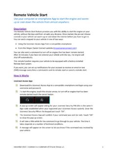
10 To release a wire, press down on the lever. When installed correctly, the release lever of the terminal block will lower to indicate engagement. Tug on the wires to ensure they are engaged in the : If you are replacing an existing thermostat, use the stickers as a guide when inserting the wires into the ecobee3 terminal you need help with the wiring, refer to the reference diagrams at the back of this guide : For conventional heating and cooling systems, see page 29. For heat pumps (air or geothermal), see page 30. For boilers or radiant heat systems, see page 31. For accessory devices like dehumidifiers, humidifiers, or ventilators, see pages 32 35.