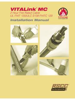
Transcription of Installation Guide For VitaLink MC System 120 - RSCC
1 Installation Guide For VitaLink MC. System 120. Inner Jacket VitaLink MC Proprietary Fire-Roc layer Conductor System 120 Annealed copper UL Listed E38918. 90 C, 600 Volt NEC Type MC. UL Classified R15365. Fire Resistive Cable Armor Insulation Continuously welded and Proprietary 480 Volt corrugated copper Fire-Roc layer Scope VitaLink MC is a unique cable which offers superior exposure. The specifications for the protective System and fire endurance capabilities along with the well established its assembly are important details in the development of benefits & features associated with NEC Type MC cable the ratings. designs. This cable is specifically designed to meet the These protective systems are evaluated by the fire circuit integrity requirements in the National Electric ex posure and water hose stream test as described in Code (NEC), NFPA 72, 130 and 502.
2 UL 2196 Test for Fire Resistive Cables . Ratings apply only to the entire protective System assembly. Individual Introduction components and materials are designated for use in a The following Installation instructions on VitaLink specific System (s) for which corresponding ratings have MC which details the System 120 instructions and the been developed and are not intended to be interchanged optional use of a junction box at electrical switch gear/ between systems. Ratings are not assigned to individual equipment. Complete Installation information can be System components or materials. found in the RSCC Wire & Cable LLC Installation Authorities having jurisdiction should be consulted in Manual (Technical Manual 2014). The national electrical all cases as to the specific requirements covering the code as well as all applicable rules and regulations, Installation and use of these Classified systems.
3 Including federal, state, local, and municipal laws shall The following instructions are for the VitaLink MC. be followed. UL System No. 120, a 1 hour and 2 hour fire rated System . This cable is only rated at 480 volts (conductor Electrical Circuit Integrity System to conductor) when used for a 1 hour or 2 hour fire Electrical Circuit Integrity Systems consist of components resistive cable. and materials that are intended for Installation as protection for specific electrical wiring systems, with respect to the These requirements must be followed to maintain the disruption of electrical circuit integrity upon exterior fire 1 hour and 2 hour rating in a fire rated area. RSCC Wire & Cable LLC 2014 20 Bradley Park Road East Granby, CT 06026 USA 800-327-7625 Tel: 860-653-8300 Fax: 860-653-8301 Terminating VitaLink MC at Junction Box Electrical Switch Gear/Equipment Min.
4 12" Splice Raceway A junction box is optional on either end of the fire UL. rated cable in the fire rated room per the following (see Listed VitaLink MC Cable Figure 1): Pliable Seal MC. Connector a) Once the cable enters the fire rated room, a minimum of 12 inches, terminate the VitaLink MC cable into See Note 3 Fire Pump the appropriate size junction box per the NEC Article Fire Rated Controller Wall 314 (see Table 1). Use a UL listed MC connector Or suitable for a corrugated copper sheath, a UL listed Transfer Switch lock nut and insulating bushing to terminate the cable to the box. Connector should be suitably grounded. Equipment grounding conductors should be carried Figure 1. through and maintained as required. b) Using the appropriate raceway for the specified area, Table 1. Box Size per NEC connect the junction box to the equipment.
5 Minimum Box Length for Straight Through Splice c) Install appropriate wiring between the junction box 3/C Conduit Box 4/C Conduit Box AWG/Kcmil Size Size AWG/Kcmil Size Size and the equipment. 8 1 8 8 1 8. 6 1 8 6 10. d) Splice VitaLink MC to the wire using an approved 4 10 4 10. method. Note a transition splice may be required 3 10 3 12. based on ampacity considerations. 2 10 2 12. 1 2 16 1 2 16. 1/0 2 16 1/0 2 16. e) Seal the end of the raceway in the junction box to 2/0 2 16 2/0 20. keep gases from migrating down into the equipment 3/0 2 16 3/0 20. in the case of a fire. This may be done using a 4/0 20 4/0 20. 250 20 250 3 24. pliable compound. 350 3 24 350 28. 500 3 24 500 28. Note 1: All wiring methods and Installation procedures shall comply with the National Electri cal Code and Minimum Box Size for Angle Splice local amendments.
6 3/C Conduit Box 4/C Conduit Box AWG/Kcm Size Size AWG/Kcm Size Size Note 2: NEC Article 110-14 should be considered in 8 1 6 8 1 6. regard to the temperature limit of the wiring to the 6 1 6 6 equipment. The VitaLink MC cable may be sized at 4 4 90 C if so desired. 3 3 9. 2 2 9. 1 2 12 1 2 12. 1/0 2 12 1/0 2 12. 2/0 2 12 2/0 15. 3/0 2 12 3/0 15. 4/0 15 4/0 15. 250 15 250 3 18. 350 3 18 350 21. 500 3 18 500 21. All conduit and box sizes in inches. Based on flexible metal conduit without a ground wire, and RHW-2 conductor size per the NEC. RSCC Wire & Cable LLC 2014 20 Bradley Park Road East Granby, CT 06026 USA 800-327-7625 Tel: 860-653-8300 Fax: 860-653-8301 RSCC VIT-MC-60 02/2014.
