Transcription of Installation Guidelines - Generac Power Systems
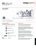
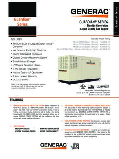
1 Installation GuidelinesForManual Transfer Switches 6335 / 6382 This manual should remain with the manual must be used in conjunction with the appropriate owner s manual.*NOT INTENDED FOR USE IN CRITICAL LIFE SUPPORT APPLICATIONS.*ONLY QUALIFIED ELECTRICIANS OR CONTRACTORS SHOULD ATTEMPT Installation !iiTransfer Switch Installation GuidelinesForwardINTRODUCTION: Thank you for purchasing a Generac Transfer Switch to safely connect a portable generator to the load center in your home or business (single phase only) for standby Power applications. Product features include: Generator and Utility Mains mechanically interlocked preventing utility or generator Power back feed. Full branch circuit protection with Siemens circuit breakers. 12 gauge High Corrosion-resistant aluminum cabinet. Ample ground and neutral termination positions for all branch circuits. Extra spaces for branch circuit breakers. Subfeed lugs provided to feed additional downstream panels or to expand beyond 16 circuits.
2 Accepts a Switched Neutral Kit (Model 6297). See Note on Neutral Bonded Generators found on page unit is a combination indoor/outdoor transfer switch and distribution panel. It can be used as service entrance equipment for 200 Amp services. In addition to being a transfer switch, this unit provides additional circuits for outdoor applications such as air conditioner compressors, sewage lift pumps, boat docks, outbuildings, garages, pump houses, barns and the like. These 200 amp series models will accommodate 12 single pole transfer switch is made up of five basic amp rated Utility Main Main 30 or 50 amp 125/250 volt inlet pre-wired to the generator mechanical safety interlock that prevents both Mains from being ON at the same set of sub-feed lugs to handle cable up to 4/0 AWG to feed the house Main THIS MANUAL THOROUGHLY. This manual has been prepared to familiarize personnel involved with the Installation of transfer switches with the manufacturer s Installation requirements.
3 Information and instructions con-tained herein are not intended to replace or supersede, local, state, or national safety, electrical, and building codes pertaining to such installations. Applicable laws, codes, and standards must always take precedence over the recom-mendations contained herein. Always check with the local Authority Having Jurisdiction (AHJ) for the codes or stan-dards that authorized dealers or qualified, competent Installation contractors or electricians thoroughly familiar with applica-ble codes, standards, and regulations should install this standby electric Power system . The Installation must be in strict compliance with all codes, standards, and is not intended that this manual be used by any unqualified person for the purpose of installing a transfer switch. Installation , inspection, and testing of the system must be attempted only by competent, qualified electricians or instal-lation contractors who are familiar with the equipment and with all Installation codes and would be impossible to provide details for every Installation configuration.
4 For this reason, much of the information in this manual is general in nature. Illustrations of typical installations are not intended to serve as specific Installation plans, but may be used in the planning and design process when considering the selection and purchase of a genera-tor set for standby Power applications. Always have the unit specific drawings and manuals on hand before beginning any a portable generator is used to Power electrical load circuits normally powered by a utility Power source, it is required by code to install a transfer switch. The transfer switch must effectively isolate the electrical system from the utility distribution system when the generator is operating. Failure to isolate an electrical system by such means may result in damage to the generator and may also result in injury or even death to utility Power workers due to backfeed of electrical the transfer switch has been installed, do nothing that might render the Installation in non-compliance with such codes, standards, and regulations.
5 Every effort was made to ensure that the information in this manual was both accurate and complete at the time it was released. However, the manufacturer reserves the right to change, alter, or otherwise improve this product at any time without notice.* Transfer Switch Installation GuidelinesiiiSection 1 Introduction .. Safety Rules .. General Hazards .. Electrical Hazards .. Fire Hazards .. Explosion Hazards .. Standards Index .. 2 Section 2 Required Tools .. Compatible Circuit Breakers Types .. Specifications .. Transfer Switch Installation .. 4 Section 3 Transferring from Utility Power to Generator Power .. Transferring from Generator Power to Utility Power .. 7 WARNING!California Proposition 65 Engine exhaust and some of its constituents are known to the state of California to cause cancer, birth defects, and other reproductive !California Proposition 65 This product contains or emits chemicals known to the state of California to cause cancer,birth defects, and other reproductive of ContentsForward.
6 IiTable of ContentsivTransfer Switch Installation GuidelinesThis page intentionally left Switch Installation Guidelines1 Section 1 IntroductionThank you for purchasing a Generac Transfer Switch to safely connect a portable generator to your home or business (single phase only). Use where the main electrical panel is located indoors. This product is suitable for service entrance Safety RulesThroughout this publication, DANGER, WARNING, CAUTION, and NOTE boxes are used to alert personnel to special instructions about a particular operation that may be hazardous if performed incorrectly or carelessly. Observe them carefully. They indicate:Indicates a hazardous situation or action that, if not avoided, will result in death or serious a hazardous situation or action that, if not avoided, could result in death or seri-ous a hazardous situation or action that, if not avoided, could result in minor or mod-erate : Notes provide additional information important to a procedure or safety warnings cannot eliminate the hazards they indicate.
7 Observing safety precautions and strict compliance with the special instructions while performing the action or service are essential to preventing commonly used safety symbols accompany DANGER, WARNING, and CAUTION boxes and the type of informa-tion each indicates:This symbol points out important safety information that, if not followed, could endanger personnel and/or symbol represents the potential for an Explosion symbol represents the potential for a Fire symbol represents the potential for an Electrical Shock THESE INSTRUCTIONS. This manual contains important instructions that should be followed during Installation of the transfer switch. The manufacturer suggests that these safety rules be copied and posted in potential hazard areas. Safety should be stressed to all installers, operators, potential operators, and service and repair technicians for this manufacturer cannot anticipate every possible circumstance that might involve a hazard.
8 The warnings in this manual, and on tags and decals affixed to the unit, are not all-inclusive. If using a procedure, work method, or operating technique the manufacturer does not specifically recommend, ensure that it is safe for others. Also make sure the pro-cedure, work method, or operating technique used does not result in unsafe General Hazards For safety reasons, the manufacturer recommends that this equipment be installed, serviced, and repaired by an Authorized Service Dealer or other competent, qualified electrician or Installation technician who is familiar with all applicable codes, standards, and regulations. Ensure that the transfer switch is installed, operated, and serviced in accordance with the manufacturer s instruc-tions. Following Installation , do nothing that might render the unit unsafe or in noncompliance. $!+ Safety2 Transfer Switch Installation Guidelines Keep the area around the transfer switch clean and uncluttered.
9 When working on this equipment, remain alert at all times. Never work on the equipment when physically or men-tally fatigued. Inspect the portable generator regularly, and promptly repair or replace any worn or damaged components using only factory approved parts and Electrical Hazards All generators produce dangerous electrical voltages and can cause fatal electrical shock. Utility Power delivers extremely high and dangerous voltages to the transfer switch as well as the generator when it is in operation. Avoid contact with bare wires, terminals and other connections. Ensure all covers, guards, and barriers are in place, and that they are properly secured and/or locked before operation. If work must be done around an oper-ating unit, stand on an insulated, dry surface to reduce potential shock hazard. Do not handle any kind of electrical device while standing in water, while barefoot, or while hands or feet are wet.
10 DANGEROUS ELECTRICAL SHOCK MAY RESULT. If it is necessary to stand on metal or concrete while installing, operating, servicing, or repairing this equipment, lay down a dry wooden platform and cover with insulated mats before beginning. Verify that the portable generator is properly grounded. Wire gauge sizes of electrical wiring, cables, and cord sets must be adequate to handle the maximum electrical current (ampacity) to which it will be subjected. Before installing or servicing equipment, verify that all Power voltage supplies are positively turned off at their sources. Failure to do so can result in hazardous and possibly fatal electrical shock. Connecting a portable generator to an electrical system normally supplied by an electric utility is by means of the transfer switch so as to isolate the generator s electric system from the electric utility distribution system when the portable generator is operating.