Transcription of Installation Instructions Fuel Gauge - Faria Beede
1 fuel GaugeInstallation InstructionsHookup Function Hookup Function + Positive + Positive Lights Lights fuel Signal Ground Ground fuel Signal Connector DT06-4S Connector 12162189 Contact 1062-16-0122 Contact 12124075 Wedge Lock W4S Plug 12034413 Plug 114017 Standard Case Wire connectionsConnectorized Case Wire connectionsIS0008e ECR6933 7/2007IS0008e ECR6933 7/2007 Deutsch ConnectorPackard ConnectorCAUTION: Disconnect the battery during Installation . Tighten nuts on back clamp only slightly more than you can tighten with your fingers. Six inch- pounds of torque is sufficient. Over tightening may result in damage to the instrument and may void your warranty. These Instructions concern only fuel Gauge installations. SPECIAL CAUTION should be taken when working on or near tanks that have, or have had, fuel in them.
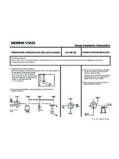
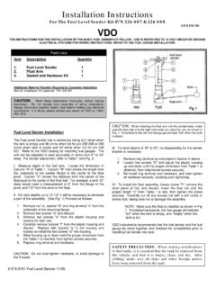
2 1. Be certain to use stranded, insulated wire not lighter that 18 AWG that is approved for marine Cut a 2-1/16 diameter hole in the dash and mount the Gauge with the back clamp supplied. For connectorized cases be sure to cut a .175 wide by .115 deep notch to accept the key on the case. See detail on next page.(See diagram on the next page for connections) Standard Case3. Connect a wire to the Gauge stud marked S (signal) and secure with nut and lock washer. Connect opposite end to the fuel level sender s signal wire or terminal. It is recommended that insulated wire terminals, preferably ring type, be used on all connections to the Gauge , except lighting, which requires 1/4 female blade terminals. 4. Connect a wire to the Gauge stud marked I (ignition) and secure with nut and lock washer.
3 Connect opposite end to a 12 VDC circuit that is activated by the ignition switch. 5. Connect a wire to the Gauge stud marked GND (ground) and secure with nut and lock washer. Connect opposite end to the boat s electrical ground, generally available in several locations at or near the instrument panel. 6. Connect the blade terminal adjacent to the twist-out light assembly to the positive + side of the instrument lighting circuit. No separate ground is required for lighting. NOTE: To change light bulb, twist black socket assembly one-eighth turn counter clockwise until it pops out. Bulb pulls out of socket assembly. It is a GE No. 161 instrument lamp. Connectorized Case3. Insert a wire with appropriate contact to the fuel Signal function of the connector.
4 Connect the opposite end to the fuel level sender s signal wire or Insert a wire with the appropriate contact to the + (positive) function of the connector. Connect the opposite end to a 12 Vdc circuit that is activated by the ignition Insert a wire with appropriate contact to the ground function of the connector. Connect the opposite end to the boat s electrical ground, generally available in several locations at or near the instrument Insert a wire with appropriate contact to the light function of the connector. Connect the opposite end to the positive portion of the lighting circuit. Insert the connector into the back of the case. NOTE: To change the light bulb, twist the socket assembly counterclockwise until it pops out. A 12V fuel Gauge requires an Oshino OL-4186NW-001972 or equivalent technical assistance, contact Faria Marine Instruments Customer Service between 8:30 AM and 5:30 PM Eastern time weekdays at (860) 848-9271 or (800) 473-2742.
5 7. Reconnect the battery. 2- 1/16 connector caseFuel GaugeInstallation InstructionsHookup Function Hookup Function + Positive + Positive Lights Lights fuel Signal Ground Ground fuel Signal Connector DT06-4S Connector 12162189 Contact 1062-16-0122 Contact 12124075 Wedge Lock W4S Plug 12034413 Plug 114017 Standard Case Wire connectionsConnectorized Case Wire connectionsIS0008e ECR6933 7/2007IS0008e ECR6933 7/2007 Deutsch ConnectorPackard ConnectorCAUTION: Disconnect the battery during Installation . Tighten nuts on back clamp only slightly more than you can tighten with your fingers. Six inch- pounds of torque is sufficient. Over tightening may result in damage to the instrument and may void your warranty. These Instructions concern only fuel Gauge installations. SPECIAL CAUTION should be taken when working on or near tanks that have, or have had, fuel in them.
6 1. Be certain to use stranded, insulated wire not lighter that 18 AWG that is approved for marine Cut a 2-1/16 diameter hole in the dash and mount the Gauge with the back clamp supplied. For connectorized cases be sure to cut a .175 wide by .115 deep notch to accept the key on the case. See detail on next page.(See diagram on the next page for connections) Standard Case3. Connect a wire to the Gauge stud marked S (signal) and secure with nut and lock washer. Connect opposite end to the fuel level sender s signal wire or terminal. It is recommended that insulated wire terminals, preferably ring type, be used on all connections to the Gauge , except lighting, which requires 1/4 female blade terminals. 4. Connect a wire to the Gauge stud marked I (ignition) and secure with nut and lock washer.
7 Connect opposite end to a 12 VDC circuit that is activated by the ignition switch. 5. Connect a wire to the Gauge stud marked GND (ground) and secure with nut and lock washer. Connect opposite end to the boat s electrical ground, generally available in several locations at or near the instrument panel. 6. Connect the blade terminal adjacent to the twist-out light assembly to the positive + side of the instrument lighting circuit. No separate ground is required for lighting. NOTE: To change light bulb, twist black socket assembly one-eighth turn counter clockwise until it pops out. Bulb pulls out of socket assembly. It is a GE No. 161 instrument lamp. Connectorized Case3. Insert a wire with appropriate contact to the fuel Signal function of the connector.
8 Connect the opposite end to the fuel level sender s signal wire or Insert a wire with the appropriate contact to the + (positive) function of the connector. Connect the opposite end to a 12 Vdc circuit that is activated by the ignition Insert a wire with appropriate contact to the ground function of the connector. Connect the opposite end to the boat s electrical ground, generally available in several locations at or near the instrument Insert a wire with appropriate contact to the light function of the connector. Connect the opposite end to the positive portion of the lighting circuit. Insert the connector into the back of the case. NOTE: To change the light bulb, twist the socket assembly counterclockwise until it pops out. A 12V fuel Gauge requires an Oshino OL-4186NW-001972 or equivalent technical assistance, contact Faria Marine Instruments Customer Service between 8:30 AM and 5:30 PM Eastern time weekdays at (860) 848-9271 or (800) 473-2742.
9 7. Reconnect the battery. 2- 1/16 connector caseFuel GaugeInstallation InstructionsHookup Function Hookup Function + Positive + Positive Lights Lights fuel Signal Ground Ground fuel Signal Connector DT06-4S Connector 12162189 Contact 1062-16-0122 Contact 12124075 Wedge Lock W4S Plug 12034413 Plug 114017 Standard Case Wire connectionsConnectorized Case Wire connectionsIS0008e ECR6933 7/2007IS0008e ECR6933 7/2007 Deutsch ConnectorPackard ConnectorCAUTION: Disconnect the battery during Installation . Tighten nuts on back clamp only slightly more than you can tighten with your fingers. Six inch- pounds of torque is sufficient. Over tightening may result in damage to the instrument and may void your warranty. These Instructions concern only fuel Gauge installations. SPECIAL CAUTION should be taken when working on or near tanks that have, or have had, fuel in them.
10 1. Be certain to use stranded, insulated wire not lighter that 18 AWG that is approved for marine Cut a 2-1/16 diameter hole in the dash and mount the Gauge with the back clamp supplied. For connectorized cases be sure to cut a .175 wide by .115 deep notch to accept the key on the case. See detail on next page.(See diagram on the next page for connections) Standard Case3. Connect a wire to the Gauge stud marked S (signal) and secure with nut and lock washer. Connect opposite end to the fuel level sender s signal wire or terminal. It is recommended that insulated wire terminals, preferably ring type, be used on all connections to the Gauge , except lighting, which requires 1/4 female blade terminals. 4. Connect a wire to the Gauge stud marked I (ignition) and secure with nut and lock washer.