Transcription of INSTALLATION INSTRUCTIONS MECHANICAL GAUGES
1 INSTALLATION INSTRUCTIONSMECHANICAL GAUGES2650-1606-00 OVER-TIGHTENING OF VENT SCREW WILL DAMAGE READING1 PSI Low 1 PSI HighCONDITION30 F. Temp. Rise2000 Ft. Altitude IncreaseNOTE: Some late model vehicles use electronic sensors in their pressure and temperature senders for engine control functions. Before removing the original sender, we recommend that you contact your automotive dealer to be sure no critical functions will be gauge may be mounted in-dash or in the Auto Meter custom mounting solutions. Secure gauge with mounting clamps supplied. 2-1 16" GAUGES mount in 2-1 16" diameter hole, 2-5 8" GAUGES mount in 2-5 8" diameter hole. CAUTION: DO NOT make severe bends in the capillary tubing. It may break internally, thus, voiding the warranty. DO NOT remove capillary tubing from Cut a 7 8" dia. hole in firewall. Place grommet on capillary tubing. A slit must be made in the grommet to accomplish this. Route sensing bulb through firewall and secure grommet in the 7 8" hole.
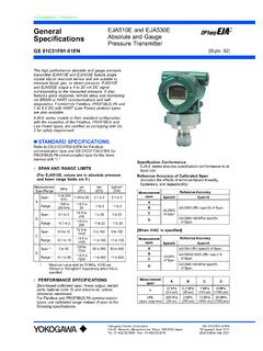
2 QUESTIONS:If after completely reading these INSTRUCTIONS you have questions regarding the operation or INSTALLATION of your instrument(s), please contact Auto Meter Technical Service at may also email us at information can also be found at Insert and tighten mounting nut in the 1 2" NPT port on engine. (For engines with a 3 8" NPT port use Auto Meter adapter no. 2263). Insert temperature sensing bulb in the mounting nut and carefully tighten sealing nut, while holding mounting nut. The Oil Temperature gauge usually requires drilling a hole and welding the Auto Meter no. 2261 steel weld fitting in the oil pan. Be sure to check for adequate internal clearances for the temperature sensing bulb. Install temperature sensing bulb as described Make sure gauge tubing is free from hazard of moving parts or hot engine Start engine and thoroughly inspect INSTALLATION for any Twist in light socket assembly and connect one wire to dash lighting circuit or other 12V power source and the other wire to a good ScrewTemperature GaugesUSE TEFLON SEALINGTAPE OR SEALINGCOMPOUND ONPIPE THREADS+12 VOLT LIGHTINGGROUNDINTERNAL LED LIGHTED MODELSV enting for Liquid Filled GAUGES OnlyAuto Meter s Pro Comp Liquid Filled GAUGES are equipped with a vent screw on the top of the case.
3 Internal case pressure can change due to altitude, barometric pressure , and temperature, causing an inaccurate or off zero reading on more sensitive low pressure GAUGES such as 0-15 psi fuel pressure , vacuum, boost, and vacuum/boost GAUGES . To prevent this it is recommended that the gauge be the vent screw in the upright position, turn the screw two turns counterclockwise to equalize the gauge case pressure . This allows the gauge to breathe and self on Ultra-Nite (Glow In The Dark)The glow in the dark coating on the dial of the Ultra-nite gauge may turn gray if exposed to direct sunlight for extended periods of time. When the car is not being used and will be in direct sunlight for long periods of time, place the provided red plastic cover on the Ultimate LED Lighting UpgradeAvailable through your local speed shop or favorite Auto meter dealer, these intense LED bulbs simply replace the standard 161, 168, 193, or 194 light bulbs used in most Auto meter GAUGES , tachometers, and speedometers.
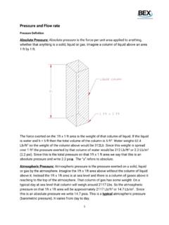
4 Smaller LED bulbs are available for tachometers that feature the small twist in light on the front tachometer. LED Replacement Kits are sold one per package. 3284 Red LED Replacement Kit 3294 Red LED, Small 3285 Green LED Replacement Kit 3295 Green LED, Small 3286 Blue LED Replacement Kit 3296 Blue LED, Small 3287 Amber LED Replacement Kit 3297 Amber LED, Small CONNECT TO 12V LIGHTINGCONNECT TO GOOD GROUNDSEALING NUTSEALING TUBINGTEMPERATURE SENSOR 1 2 NPT MOUNTING NUT FOR 3 8 NPT USE NO. 2263 LARGE RUBBER GROMMET(SMALL GROMMET NOT USED WITH TEMP. gauge )MOUNTING BRACKETTHUMB NUTLOCKWASHERM eter AdaptersIf this product is to be installed on a vehicle requiring metric fittings, please contact your local Auto Meter dealer to purchase metric adapters. A complete listing of the fittings available can be found in our catalog or online at NUTNOTE: DO NOT LOOSEN PORT NUT OR gauge MAY BE NUTUSE TEFLON SEALING COMPOUND ON PIPE THREADS4" NPT ADAPTER8" NPT ADAPTERFOR PRESSUREGAUGES ONLYSMALLGROMMETNYLON TUBING11 FERRULEFERRULELOCK WASHERTHUMB NUTORORFERRULEADAPTERT-FITTINGFOR BOOST/VACUUM GAUGESONLY COMPRESSIONNUTCOMPRESSIONNUTCOMPRESSIONN UTFERRULEFERRULEORFOR VACUUMGAUGES ONLY VACUUM HOSET-FITTINGNYLON TUBING8" CONNECTOR1 CONNECT TO12V LIGHTINGCONNECT TOGOOD GROUNDTo Blower Outlet PortCHECK VALVE FLOW ARROW MUST POINT TOWARD gauge AFTER INSTALLATIONCONNECTOR1 8 NPTF (FEMALE)x SAE 37 MALE FLARECONNECTOR1 8 NPTF (Male)x SAE 37 Male FlareFLOWUSE SEALING COMPOUND ON ALL PIPE THREAD JOINTSBLOWER W/MEMORY PLUMBING MUST BE LEAK TIGHT TO INSURE AN ACCURATE MEMORY STEEL BRAIDED TUBING (TYPICAL)HARDWARE INCLUDED IN KITCONNECTOR1 8 NPTF (FEMALE)x SAE 37 MALE FLARECONNECT TO GROUNDCONNECT TO 12V DASH LIGHTINGTEE 1 8 -27 NPTFTHUMB NUTLOCKWASHERMOUNTING BRACKETBLEED VALVENOTE.
5 Keep line clear of moving parts or hot engine Secure a 1 8"-27 NPTF female x SAE male flare connector to the bleed Using the nut and lock washer provided, secure the bleed valve and connector assembly in-dash or wherever it is convenient for the Connect length of braided stainless steel tubing between the tee on back of gauge and the bleed Start engine and thoroughly check for any leaks. When engine is shut off, gauge should not leak down until bleed valve is pushed. If gauge leaks, check and tighten all Connect the WHITE light wire to dash lighting circuit or other 12V source. Connect the BLACK light wire to a good engine ground. (which applicable)1. Secure two 1 8"-27 NPTF x #4 SAE 37 flare connectors to the 1 8"-27 NPTF tee as shown in the INSTALLATION above. NOTE: The connector flare (37 ) must be compatible with the ends on the stainless steel braided tubing. Auto Meter braided stainless steel tubing no. 3227 and 3228 include #4 SAE 37 flare female swivel Drill 3 8" dia.
6 Hole and install rubber grommet where pressure line passes through firewall into engine Secure two 1 8"-27 NPT female x SAE 37 male flare connectors to the check valve as shown above. Secure the check valve and connector assembly to one end of a length of braided stainless steel tubing. NOTE: The arrow on the check valve must be pointing toward the gauge as shown in the diagram Secure the opposite end of the tubing and check valve assembly to the tee on the back of the gauge . Route the pressure line through the firewall into the engine compartment. Connect another length of braided stainless steel tubing between the check valve and the blower outlet port. Blower with MemoryNOTE: To insure accurate memory readings DO NOT mount check valve directly to gauge or blower. Excessive vibration may cause : Some late model vehicles use electronic sensors in their pressure and temperature senders for engine control functions. Before removing the original sender, we recommend that you contact your automotive dealer to be sure no critical functions will be disrupted.
7 With pressure GAUGES , it is beneficial to add a T-fitting to install your new gauge and to keep the warning light operational. This allows you to monitor the pressure and still have a warning light to indicate emergency GAUGES may be mounted in In-dash holes, or in Auto Meter custom mounting Solutions. Secure gauge with mounting clamps supplied. 2-1 16 GAUGES mount in 2-1 16 diameter hole, 2-5 8 GAUGES mount in 2-5 8 diameter Drill 3 8 dia. holes and install rubber grommet where pressure or vacuum line passes through sheet metal, such as Attach nylon pressure line to fitting on back of gauge using adapter, ferrule, and compression nut as shown in diagram above. Route line through grommet to engine compartment. Connect line to pressure port on engine by using 1 8 adapter (1 4 if needed), ferrule and compression nut for pressure GAUGES or 1 8 connector and T-fitting for vacuum Make sure line is free from hazard of moving parts or hot engine components.
8 It is recommended that Auto Meter 3224 copper tubing kit be used where a potential hazard Start engine and thoroughly check INSTALLATION for Twist in light socket assembly and connect one wire to dash lighting circuit or other 12V power source and the other wire to a good , Vacuum & Boost GaugesGROUNDINTERNAL LED LIGHTED MODELS+12 VOLT LIGHTINGNOTE: DO NOT OVER TIGHTEN ADAPTER FITTING OR gauge MAY BE : DO NOT LOOSEN PORT NUT OR gauge MAY BE NUTNOTE: DO NOT OVER TIGHTEN FITTING OR gauge MAY BE : DO NOT LOOSEN PORT NUT OR gauge MAY BE BRACKETWARNING: Use Teflon tape or sealant only where indicated. Do not use oil on : This gauge is supplied with a special restrictor fitting that Must be installed on the braided line leading to the nitrous : USE ONLY -4AN high pressure stainless steel braided line when installing this gauge . All fittings must have a minimum working pressure of 2000 If you are not familiar with nitrous oxide systems and their installations do not install this gauge .
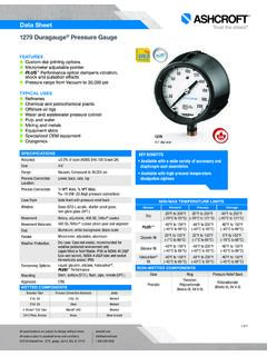
9 Have a qualified mechanic install it for Determine where the nitrous gauge will be mounted and the source of the pressure (bottle outlet or nitrous solenoid inlet fitting). Then determine the length of steel braided line required. (Auto Meter offers three -4AN stainless steel braided line kits: Model #3227- 3 feet, Model #3228- 6 feet, Model #3229- 4 feet)3. Secure the -4AN stainless steel braided line to the back of the gauge as shown in the illustration. 4. Install gauge in appropriately sized dashboard hole or use under dash panels. Secure gauge with the mounting bracket provided. NOTE: If alternate gauge mounting is used other than in-dash or under dash, mounting provisions may have to be determined by the Make sure the nitrous bottle valve is Secure an in-line gauge adapter (eg. NOS part #16770 or #16771) in a vice. Install the special restrictor fitting (supplied with gauge ) in the in-line gauge adapter.
10 Do not over tighten as this may result in stripped threads or a broken Remove the main nitrous feed line from the bottle or the nitrous solenoid. Install the in-line gauge adapter with the special restrictor fitting either on the nitrous bottle or nitrous solenoid. Re-install the main nitrous feed line. Install the braided line from the nitrous gauge to the restrictor Open the nitrous bottle valve. NOTE: Test all fittings and hoses for any leakage. If any leaks are detected, determine the cause of the leak and repair. Do not operate vehicle if any leaks are BottleNitrous SolenoidSpecial Restrictor Fitting (Included)Main Nitrous FeedSpecial Restrictor Fitting (included)In-Line gauge AdapterIn-Line gauge AdapterINOUTS teel braided line to gaugeSteel braided line to gauge -4AN fitting with wrench flat. (use caution, do not to over tighten)Good GroundTo Dash 12V (+) LightingBrake pressure GAUGES WARNING: ONLY double flared steel brake line may be used to install this gauge .